| Author |
Message |
    
Opto
| | Posted on Tuesday, March 16, 2004 - 03:44 am: | 


|
This maybe could be done with 2 resistors and one 5V zener, the power in (12V) is already there. The expensive bit would be the connector. |
Darthane
| | Posted on Tuesday, March 16, 2004 - 04:05 am: |
|
There are plenty of ways to do it. They're based on the above extrapolation being correct, though, and while it all sounds good I don't really know...(sometimes I'm such a good BSer I fool myself!)
If the ECM pin that's grounding can accept ~200mA you could steal a 5V signal by tapping into one of the other regulated sensors and have the ECM ground the circuit, activate the relay, and supply 5V to the feedback line.
If I had a 12 to play around on I'd monkey with it, but my Firebolt doesn't have one of these fancy doohickies! Just seems like an awful lot of trouble to get rid of what? 8 oz? A pound with the jumper harness? How much does that thing weigh?
See, connectors I might be able to come up with, provided I can get a part number.
Bryan |
Blake
| | Posted on Tuesday, March 16, 2004 - 08:55 am: |
|
I recall with fair certainty that the exhaust valve is actuated based upon engine speed AND throttle position (WOT I believe), and the valve is either commanded to be open or closed, there are no partially open commands from the ECM. Don't expect any comments from anony on this issue, though you might find a licensed racer who can talk to Henry Duga about the issue. |
Blake
| | Posted on Tuesday, March 16, 2004 - 08:57 am: |
|
Of course he'll simply tell you to use the Race ECM. |
2k4xb12
| | Posted on Tuesday, March 16, 2004 - 03:28 pm: |
|
Thanks for the schematic -- apparently, it is a DC motor and not a stepper... This actually makes it a bit more difficult to fake out the ECM. Oh well -- more to think about...

edited by 2k4xb12 on March 16, 2004 |
Stot
| | Posted on Tuesday, March 16, 2004 - 10:17 pm: |
|
I wrote some servo control PIC chips a while back, they are DC and their position is determines by a 1-2ms pulse signal with 1ms intervals. A 508A Pic chip could do the job of faking the sensor easily if programmed correctly. My guess would be its open or closed so you will probably only be looking for 2 different pulse signals from the ECM and then pull the hall sensor down for one and up for the other all in real time. Course I ride a 9. 
Cya
Stot |
Opto
| | Posted on Wednesday, March 17, 2004 - 02:50 am: |
|
I don't think the ecm drives the servo directly, info from the flowchart and schematics suggests the ecm applies a ground and the control cct in the actuator then drives a dc motor all the way, and the ecm looks for 4-6V from the hall effect sensor.Then when the ground is lifted the control cct drives the motor all the way back and the sensor reads 0-1V. Will experiment this weekend. Main prob is if I throw a fault code I'll have to wait 50 run cycles for the fault to be cleared before trying plan B.
Why would I want to do this? I want to reclaim that space under the cover for something else. |
Darthane
| | Posted on Wednesday, March 17, 2004 - 05:04 am: |
|
Opto, what are you planning on trying first? |
Opto
| | Posted on Thursday, March 18, 2004 - 03:06 am: |
|
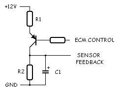
Maybe this would work, when the ecm control goes low C1 will charge up to 5V with R1 and R2 acting as a voltage divider network. When the ecm control lifts the ground, C1 discharges through R2 and goes low. Hopefully this will keep the ecm happy. Component values will have to be tried on the bench before fitting to the bike. Where's Reepicheep?
 |
2k4xb12
| | Posted on Thursday, March 18, 2004 - 11:17 pm: |
|
Has anybody actually stuck a scope on the motor feed and hall sensor to see what kinds of interaction they have? My Tektronix 475 has recently suffered a high voltage supply failure, so I can't look at the signals myself (this has prompted me to bid on another 475 on Ebay though). The circuit above looks interesting enough -- any idea what kind of charge/discharge time we're looking for in regards to C1? If so, then values should be fairly easy to nail down...
Steve. |
Opto
| | Posted on Friday, March 19, 2004 - 02:47 am: |
|
Steve, C1 charge/discharge time needs to be 0.5 sec or less - just ran the actuator up on the bench. If you can work out some ballpark figures for the cap and resistors that will save me time doing it by trial and error. Thanks, Ian. |
2k4xb12
| | Posted on Friday, March 19, 2004 - 11:09 am: |
|
Well, the rate of charge and discharge will be different, because the value of R1 will determine the charge, and R2 the discharge, and R1 needs to be a bit less than double the value of R2 to get the division we want. The charge/discharge rate is calculated by R*C. For starters, try a value of 22K for R1, 22uF for C1 and 9.1K for R3. This should give a charge rate of approx. .48 seconds and a discharge rate of approx. .2 seconds. Oh yeah, stick a resistor of about 10K on the base of the transistor to limit current.
This is a ballpark, but should give you a starting point... |
Opto
| | Posted on Wednesday, March 24, 2004 - 06:16 am: |
|
Thanks Steve, your info did help. Update: No success yet, ecm not happy, more research and testing required, info from the FM is not the whole story (the "low" from the ecm is 2.5V and the hall sensor O/P is loaded with 5V from the ecm and the hall sensor O/P is not linear, it appears to drive a flip-flop at each end of the actuator travel), will post details in KV when I get it done. |
|