| Author |
Message |
    
Reepicheep
| | Posted on Tuesday, December 31, 2013 - 04:58 pm: | 


|
LOL. I just noticed my high and low are backwards.  |
    
Bluzm2
| | Posted on Wednesday, January 01, 2014 - 11:58 am: | 


|
This thing is too cool..
I still like one of the original designs with the controller completely in the handlebars.
However I do completely understand have it remote.
The LCD information regarding charging would be a nice option. You could take this thing lots of different directions..
If it wasn't so damn cold out I could test one for you! Oh, that snow on the road thing would suck too...
Brad |
    
Reepicheep
| | Posted on Wednesday, January 01, 2014 - 12:50 pm: | 


|
Thanks Brad! The board will support the LCD, but you can make a cheap small version by not adding one on there. I can even switch controllers between the PIC18F1220 and the PIC18F1320 (same chip more ram) if I want, and just stub off all the LCD code. Only saves $1 or so though, so why bother.
The in the handlebar version was pretty cool. Trying to fit it in such a small space ended up making everything a PITA. Easier to just have a slightly bigger board you just bury under the windscreen somewhere, and run a remote wire with the thermistor up to the cartridge in the bars. That also solves the problem of different inside diameters of bars.
This one also has both an ambient (board) temp sensor and a remote grip temp sensor. I think that will let me much better tune the heating algorithms.
Truth be told, playing with this thing is just fun. It's like legos for grownups.
Still looking for packaging / PCB fabrication help if anyone is a guru in that space! It would be nice to have more professionally produced boards and a slick little enclosure to stuff them in. With all the rapid advancements in rapid prototyping, I'm a little disappointed that somebody can't just whip these things out affordably in small volumes. |
    
Bluzm2
| | Posted on Wednesday, January 01, 2014 - 04:02 pm: | 


|
Bill,
Interesting article....
http://hackaday.com/2012/06/13/ladyadas-thoughts-o n-quick-turn-and-small-run-pcb-houses/
I knew there was another reason to mount the controller remotely, the ambient temp sensor! That would really help fine tune the overshoot issue. |
    
Reepicheep
| | Posted on Wednesday, January 01, 2014 - 07:05 pm: | 


|
Thanks, these folks look interesting and affordable. $10 for an up front consult before going to fabrication (worth it as I have never done it before) and $14 for 10 boards (if I am reading their site correctly). That's a great deal. |
    
Reepicheep
| | Posted on Wednesday, January 01, 2014 - 10:28 pm: | 


|
Huge breakthrough... I was previously assuming a linear response for the thermistor. I knew it wasn't, but did some quick empirical tests and convinced me it wasn't that big a deal that it was off as previously I never actually displayed the temp.
Well, now that the temp shows on the LCD, it was bugging me that it was diverging from reality at high temps. And in fixing it, I found it REALLY was walking over the cliff, so what I was setting at 110 or so before was closer to 130. Had I known I would have addressed it even though it wasn't being displayed
So I fixed it (with some pretty elaborate math), and now track down to half a degree perfectly. It made a huge difference in how well things work in the lab.
Now I'm dialing in the heat algorithm better than ever... fun stuff. |
    
Reepicheep
| | Posted on Friday, January 03, 2014 - 12:19 pm: | 


|
Just to show how challenging a problem this is.... the plot below shows the temperature of a polly heater in a simulated handlebar (a foot of copper pipe) and what it does over 15 minutes with the latest version of my controller.
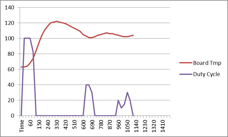
The red line shows temperature, the blue line is the power the controller is putting out. Temp is accurate, the power updates much faster than I could record so it is a guessed average by me looking at the display. Good enough to understand what is happening, not good enough to do math by.
You can see how insanely difficult it would be for some poor fool (like me) with a switch on the handlebars chasing a comfortable temperature... and this is steady state, an easy case. Toss in 60 mph at 45 degrees (which is like 20 degrees wind chill) versus 0 mph at 45 degrees (which is 45 degrees wind chill). So in one second, the controller will see an effective temperature delta of 25 or more degrees.
Good luck chasing that with a switch and not driving into the car in front of you...
I have 34 bytes of program space remaining in my PIC1330. Talk about making the best use of what is available....  |
    
Reepicheep
| | Posted on Friday, January 03, 2014 - 12:21 pm: | 


|
Oh, and the target temp set for that test was 105 degrees, and it is labelled "board temp" but it is actually the remote heater temp (which is now separate from the board temp). |
    
Prior
| | Posted on Saturday, January 04, 2014 - 08:57 am: | 


|
Bill,
That is awesome! I still have the original in my toolbox, may need to send that back for reprogramming  Some days I wish I knew more electrical stuff, most days I'm happy turning wrenches and working with hydraulics! Some days I wish I knew more electrical stuff, most days I'm happy turning wrenches and working with hydraulics!
Keep up the good work! |
    
Reepicheep
| | Posted on Saturday, January 04, 2014 - 10:44 am: | 


|
Hang it on the wall, there will be a better one coming soon enough.
Hydraulics sound like they would be much more exciting when they go wrong. 
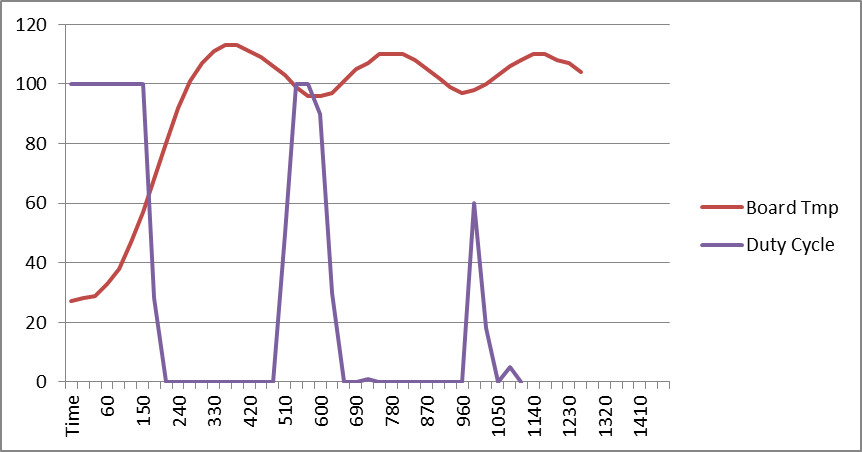
This mornings plot (new tweaks to the control algorithm, and an actual 27 degree ambient test instead of a bag of ice on the heater before the test)
|
    
Bluzm2
| | Posted on Saturday, January 04, 2014 - 12:27 pm: | 


|
Bill, you scare me!
Seriously cool stuff. Put me in line for a new one too!
Brad |
    
Reepicheep
| | Posted on Tuesday, January 07, 2014 - 06:44 pm: | 


|
It's getting dialed in really nicely, and I'm down to 30 bytes of ram left even after hand optimizing my C code, so I am probably close to having the hardware and software dialed in for this V6 uber heater.
FWIW, a polly grip heater is running at about 65 percent power to maintain 115 degrees when it is sitting on a deck covered with ice during -7 degree ambient temps with 20mph winds.
And also FWIW (probably a very valuable metric, truth be told), what you are feeling at your hands is a reflection of what you did with the power switch between 2 and 3 minutes ago. So if you wait until it gets hot to turn them back off, you have an uncomfortable 2 minutes in front of you. 
Now on to getting serious about packaging it. |
    
Reepicheep
| | Posted on Saturday, January 18, 2014 - 11:27 pm: | 


|
V6E...
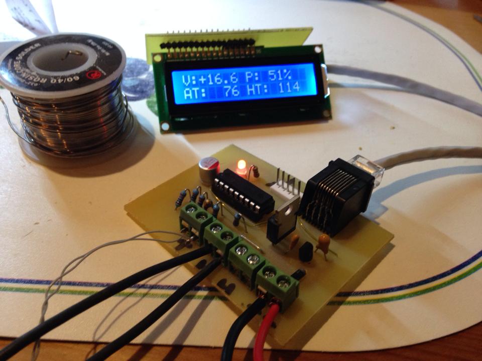
The LCD is now pulled out as a sub assembly that is optional... you can run the controller alone as a black box, or hook up the outboard LCD assembly to get the transient voltage problem detection system and temperature and power status.
V is voltage (DC) that reads about 50 times a second looking for "out of normal" readings.
If it does see an out of normal reading, it switches over to a "burst mode" and just looks for and reports transients... it reads for a 3 second window, shows the highest and lowest voltages it has seen while scanning the next 3 second window. It's cranking along at something like 300 samples per second.
The "AT" is ambient temperature measured at the board. The "HT" is the current heater temperature measured at the bars (or in a jacket, where this would work just as well).
The "P" is the current % power being put to the heating elements.
It should drive up to 80 amps, but I am only testing it with the Polly heaters, which are about 3 amps. The MOSFET has no heatsink and is cool to the touch at 3 amps. |
    
Reepicheep
| | Posted on Saturday, January 18, 2014 - 11:32 pm: | 


|
Oh, and of course it stops trying to run the heaters if the battery is not charging (i.e. the stator has blown or the engine has not been started yet).
Every time you thumb the starter button, you will drop into transient burst mode, and get a .1 volt accurate reading of the lowest voltage seen during starting... so you get a proper battery load test every time you thumb the starter. |
    
Bluzm2
| | Posted on Sunday, January 19, 2014 - 11:36 am: | 


|
Cool stuff Bill.
I know this is a prototype, is the next version goin to use SM components or discretes like the prototype? |
    
Reepicheep
| | Posted on Sunday, January 19, 2014 - 12:44 pm: | 


|
I'm at the limits of my tools with the discrete parts... It it was going to be made commercially, it could squeeze down really small, but then I can't build them in my garage.
It's getting pretty small as it is anyway.
The ethernet jack modular connector was a cool idea, especially since I had a zip lock bag full of them I had laying around that i bought for pennies on the dollar, and a crimp tool and connectors to build the cables. That part of it was awsome. But it's awfully big, so that probably has to go also, and I need to come up with some other kind of flatter connector. Then the LCD can pretty much shrink down to just the size of the LCD with a little extra thickness for the connector and circuit board.
Those Blue 16x2 LCD's are under $4 each on ebay now. It boggles the mind. |
    
Reepicheep
| | Posted on Wednesday, March 26, 2014 - 02:57 pm: | 


|
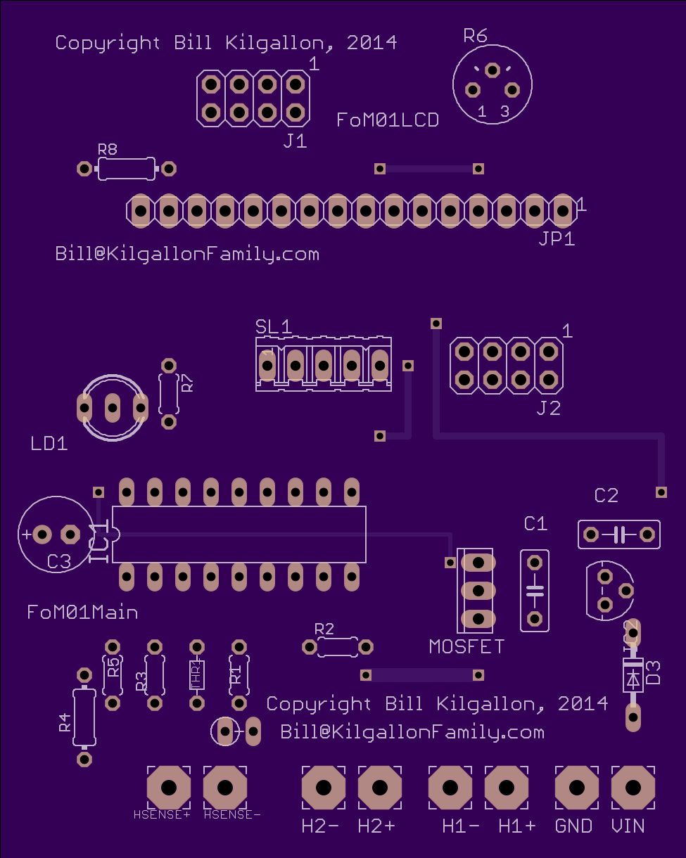
Still struggling with packaging, but I bit the bullet and ordered my first "professional" boards (rather than ones made in garage via laser printer and acid bath)...
|
    
Reepicheep
| | Posted on Wednesday, March 26, 2014 - 03:07 pm: | 


|
Top half is optional LCD module, now with lower profile connector (the Ethernet jack was cool, but by the time you make it a sandwich with the LCD the thing just got too tall). Runs fine with or without LCD.
About $12 per board for 3 prototypes with quick turnaround from a US manufacturer (OSH Park). If I go with Seed Studio I can get about 10 boards for that same amount, but their tools are less newbe friendly and I'd prefer to deal with US companies if possible.
Now back to figuring out how to make a weatherproof enclosure for them...
On that front, GE Silicone II seems to work very well (the low odor stuff, it is not acidic like normal silicone). I can get the real potting silicone for $35 or so a quart, but it has a limited shelf life so I am not ready to invest in that yet, particularly when I am still flailing trying to figure out the other aspects of the enclosure.
If anyone wants to design and prototype enclosures, all I can offer is the same kind of fun wasting of time I am doing. Give me an enclosure and I'll give you a controller.  |
    
Prior
| | Posted on Wednesday, March 26, 2014 - 10:20 pm: | 


|
Awesome! That a sweet looking board! |
    
Reepicheep
| | Posted on Wednesday, April 02, 2014 - 09:15 am: | 


|
Rewrote much of the software, and as a result I now have burst transient mode sampling at close to 10,000 samples per second, continuous display of high / low / current voltages on the optional LCD, and the tri color LED is now usable alone (without the LCD).
The tri color LED will work as follows (unless somebody has a better suggestion)
1) No heat all well... solid green LED
2) Heating all well... amber and green color alternation varying based on current duty cycle (more amber means more heat)
3) Heating over voltage... blinking on and off red LED.
4) No heating because under voltage... red and green alternating colors, more red means more dead. I calculated it out such that by the time it is all red, the bike is dead on the side of the road. I guessed that about 10 volts is when the bike just isn't going to run anymore.
13 PC Boards on the way, we will see if they work.  |
    
Prior
| | Posted on Thursday, April 03, 2014 - 07:40 am: | 


|
I think the 5 year old battery on my Uly is finally giving up the ghost- perhaps a good test specimen! |
    
Reepicheep
| | Posted on Thursday, April 03, 2014 - 10:05 am: | 


|
I'll ship you one of the prototypes. The first batch is probably only 3 boards from a US company, so hopefully will be here this month. The second batch is from a US company that uses a Chinese fabricator for the boards, and I can get 10 boards for less $$, but it will likely take longer. I tried both to see how the service and quality compares.
I got the new controller hooked up to the bike (as opposed to the test bench) last night for the first time, and it's pretty revealing with the new 10,000 samples per second burst rate.
At idle, I saw a range of voltages captured from 13.1 all the way through 14.9 volts, which was surprising to me. It's already telling me I have transients. A reasonably freshly charged battery drops to 6.2 volts on cold crank up. One that has been setting longer drops below 5 volts, and makes my controller LCD reboot (which means I can't tell how low it actually goes).
My battery is pretty marginal as well. When it finally dies and I swap it, it will be interesting to see how the readings change.
It would be useful to see if other bikes have such wide voltage swings. |
    
Reepicheep
| | Posted on Thursday, April 03, 2014 - 10:11 am: | 


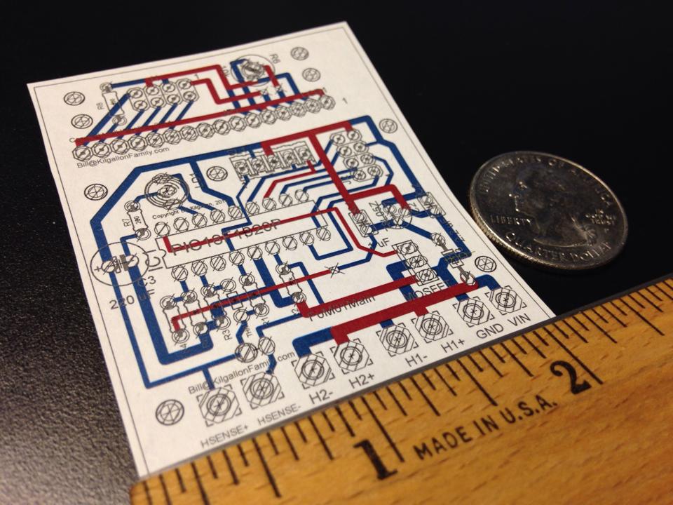
|
The bigger batch of boards is also really small now as well.... about as small as it will get without surface mount. Great fun to lay out, it is like the worlds best tetris game.
|
    
Court
| | Posted on Thursday, April 03, 2014 - 10:23 am: | 


|
This is interesting. I've got some ideas I'll collect and send. I love this stuff. |
    
Reepicheep
| | Posted on Thursday, April 03, 2014 - 12:18 pm: | 


|
Love to hear them. As I built this out I did it "right", and I have a great foundation for many other projects. Both hardware and software is *way* over designed (in a good way).
Each board probably has $9 worth of hardware at most. And 11ty million in engineering effort. 
Next step is to control heated gear, where it will work even better (I realized that half way through this project, but I wanted to finish what I started). |
    
Reepicheep
| | Posted on Thursday, April 03, 2014 - 12:20 pm: | 


|
(* Optional LCD module not included in base board price... thats another $9.  ) ) |
    
Bluzm2
| | Posted on Thursday, April 03, 2014 - 09:57 pm: | 


|
Bill,
If you need a northern climate tester count me in.
I LOVE the earlier version, it wouldn't take much to change it out since I already have the heaters.
Let me know the price of admission and I'm in...
Brad |
    
Bluzm2
| | Posted on Thursday, April 03, 2014 - 09:58 pm: | 


|
Oh yeah, testing might be delayed.
WE ARE GETTING UP TO A FOOT IF FRIGGIN SNOW TONIGHT!!!!
Man I hate this state. |
    
Reepicheep
| | Posted on Thursday, April 03, 2014 - 10:34 pm: | 


|
I will... Ordered 10 LCD's today. Parts inbound via slow boat from China. |
    
Reepicheep
| | Posted on Monday, April 14, 2014 - 09:47 am: | 


|
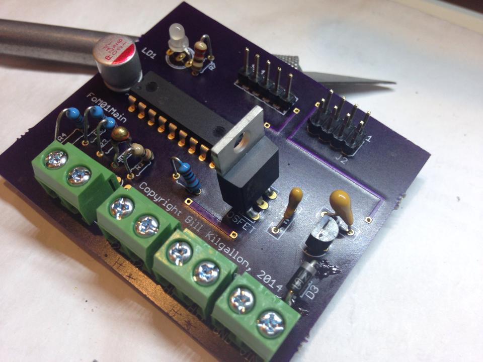
Getting pretty fancy. The LCD is cool info, but is a huge liability in terms of packaging and mounting the thing. |
    
Puddlepirate
| | Posted on Wednesday, April 23, 2014 - 02:08 pm: | 


|
Just found this thread and read it all. Great stuff!!
When I hit the states and it gets cold (haven't seen cold in 2 years), I'd be happy to buy one of these from you! |
    
Reepicheep
| | Posted on Wednesday, April 23, 2014 - 03:13 pm: | 


|
I have 13 professionally produced PC boards on the table waiting to be built. I've been tweaking the firmware again... just can't help myself.
I think I can solve the packaging problem for the actual controller fine.
The LCD will be a bit more of a challenge, so I will probably just offer it as a separate optional module (ribbon cable with quick disconnects) and leave packaging that as an exercise to the buyer if I don't work it out by then. It's really cool when the LCD is operating, but its not at all necessary for the platform to be useful.
And you could use the controller normally without the LCD until the LED goes red, then plug in the LCD (when it isn't raining) as a diagnostic tool and see what the specific problem is.
Or figure out how to package up the LCD so it can survive on the handlebars in a monsoon... |
|