| Author | Message | ||
Jerseyguy |
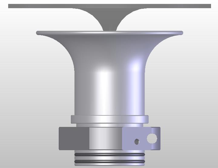
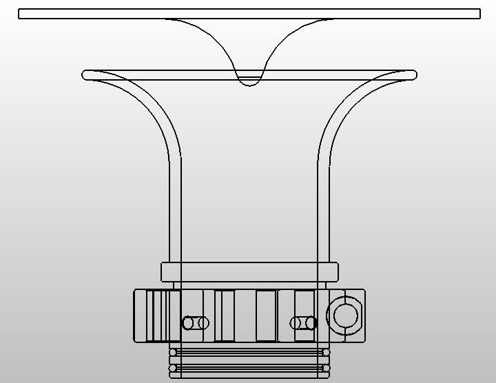
I've been toying with the idea of CNC'ing my own velocity stack out of aluminum. I really know very little on how to design one of these so I guess for starters I'll just copy the existing XB9 geometry and work out the sealing on my own. Over the holidays I had some time so I solid modeled the exact geometry of the stock Buell stack and for the hell of it I added in the 12's cover just to see the relationship. I attached some jpegs that depict this relationship for all the motor heads on BWB. Steve   | ||
M1combat |
I'm no fluid dynamics guy, but maybe decrease the radius on the outside curve? I know there are freeware programs on the web the will model fluid dynamics. My guess is that they would be able to use ACAD or Pro-E file formats. I would imagine you would get better results out of them if you modeled the entire airbox though. I seem to remember reading somewhere that the air creates a bit of a vortex inside the box and that there is more pressure on one side of the velocity stack. Also, can you rifle it or would that add too much to the cost/time of production? Looks pretty neat so far though  . . | ||
Jerseyguy |
Cost / time isn't really a factor when I'm just making one for myself. I'm not even sure if I want laminar or turbulent flow at this point. For the first one I'll probably just go with the existing geometry which looks like a laminar kind of design to me. The rubber stock body was about .120" oval and the top lip had a flatness deviation of around .070". It seems like it's got to help if these dimensions are tightened up. I wonder how much effort Buell put into this geometry. Was the stack designed specifically for the 9 or did they just copy something that worked in the past? Perhaps "Anonymous" might like to add his thoughts. Steve edited by jerseyguy on January 04, 2004 |