| Author |
Message |
    
Crazyman54783
| | Posted on Wednesday, April 29, 2009 - 05:00 pm: | 


|
I got mine apart last night. Thanks for the help.. |
    
Crazyman54783
| | Posted on Wednesday, April 29, 2009 - 05:01 pm: | 


|
The sad thing is is that the front brake side went this past weekend to so you guys should see my work bench haha rear and both front shock rebuild. |
    
Oldog
| | Posted on Friday, May 01, 2009 - 05:34 pm: | 


|
Here is my version of the tear down in a short form the job is straight forward
I spoke to I believe John at MotoPro their Phone is 844 0661 area 425 He has the 16 mm seal and dust seal for the showa, he can provide the bushings too. at the time of posting I have arranged return of all race tech items, I was not inspired with them after discovering the Boo - Boo on the site I would like to have the bike up soon
SHOWA SHOCK TEAR DOWN
ORIGINAL WORK POSTED BY Ben M2 on bad web
This condensed tear down would not be being written except for the efforts of Ben, who took the big step of trying to de-mystify the showa shock,
Some Points
The Showa “Pull shock” was not intended to be serviced but no doubt was intended to be a life time type of item, due to its working conditions they fell short of the goal,
The shocks design and construction are in many ways good quality and show clever use of wire clips to fasten and retain things
NOTE The 14.7” recall shock has a 16 mm shock shaft
The shock will require some small alterations while being disassembled these will be covered in section 2, I presume that you will layout parts as they come out and clean them, Ben goes into great detail on this, certain parts like the piston if mis assembled will not work correctly, others can be broken, pay close attention while working on the shock
Note I am not covering inspection of the parts as there is no published information on them, common sense must be used while examining the parts and reassembling them
section 1 is the removal of the spring from the shock
section 2 is disassembly of the shock
section 3 is replacement of the seals
section 4 is reassembly of the shock
section 5 is reassembly of the spring on the shock
WARNING THE SPRING AT MINIMUM PRE LOAD IS UNDER HIGH TENSION FAILURE TO PAY ATTENTION TO THE TASK AT HAND CAN RESULT IN SERIOUS INJURY,
WARNING THE OIL AND BLADDER ARE UNDER HIGH PRESSURE
YOU MUST RELEASE THE BLADDER PRESSURE BEFORE ATTEMPTING DISASSEMBLEY FAILURE TO DO SO WILL RESULT IN A BF-MESS AND AGAIN YOU CAN GET HURT.
If you are not sure if you can accomplish the repair contact Race Tech for repair assistance, the basic repair of the seals and new oil at the time of this writing was 200$ about ½ new price and about ¼ the price of a comparable after market shock.
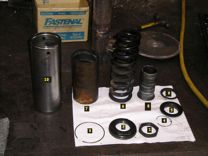
SPRING PARTS
1. Adjustment lock nut
2. Spring adjustment nut [ spring nut ]
3. Spring nut retainer
4. Spring stop retainer
5. Spring stop collar
6. Spring
7. Outer spring wear sleeve
8. Inner wear sleeve
9. Body wiper
10. Spring “CAN”
The Press tools
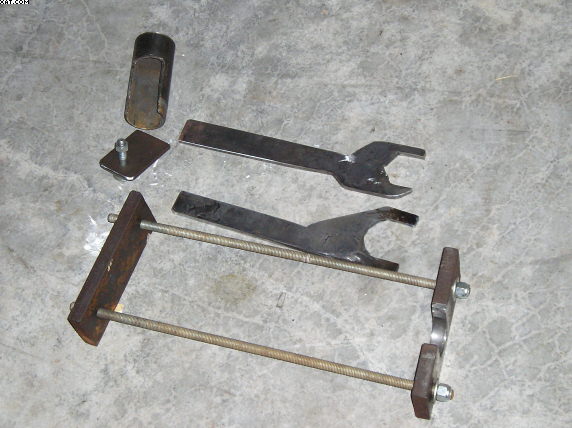
Section 1
Tools: ¾” end wrenches, press tools, picks, small screw driver, wrenches for the spring nut, lock nut, crescent wrenches, cleaner, and rags.
The Press tool consists of 2 pieces of 3 x ¾”x 7” Hot roll steel, 2, 23” lengths of ½” all thread, 2” pipe 5”~ 6” slotted one side, steel locking plate ¼” x 2” x 3”
At this point it is not necessary to depressurize or drain the shock be careful of the hose and reservoir a vice to hold the pressing tool will make the job easier.
The Pressing tool has a flat top bar and a slotted bar at the other end ( the hose end of the shock fits here and the spring can rests against it a slotted pipe is used to apply pressure to the nut and rest plate to remove the spring.
1. Remove the locking nut by unscrewing it from the shock it will screw off of the rod end . [item 1]
2. tighten the spring nut till it stops [ item 2 ]
3. fit the shock in the tool, hose end on the slotted end of the tool, take care not to pinch the hose
4. slip the pipe over the rod end of the shock
5. install the lock plate and fit it so that it bears against the slotted press plate tighten the bolt so that the plate is on the press plate
6. finger tighten the nuts on the thread rod bring the plates in contact with the shock and pipe square the plates up
7. Tighten the nuts equally and push the spring nut into the can far enough to allow removal of the retaining ring
8. pick the ring out
9. gradually slack the nuts and remove the pipe from the shock remove the spring nut from the shock
10. reset the press tool on the spring stop collar
11. tighten the press tools nuts and push down far enough to compress the spring
NOTE A RAP ON THE BODY END OF THE SHOCK MAY BE NEEDED AS THE SHOCK MAY MOVE WITH THE SPRING STOP COLLAR, HIT THE SHOCK ON THE END ONLY.
12. Remove the retaining clip
13. loosen the nuts as before watch for the shock as it may fall out of the tool once the spring stop has been removed.
14. remove the shock and set it aside
15. remove stop collar from spring
16. turn over spring “can” and slip the spring with the inner and outer sleeves and wiper
17. separate the spring and the sleeves.
18. remove lock plate from shock, set press aside
The spring is now removed.
The plastic parts two sleeves and the wiper are to prevent wear by the spring on the spring can and shock body, the sleeves must be intact and can be cleaned and set aside |
    
Oldog
| | Posted on Friday, May 01, 2009 - 05:49 pm: | 


|
Section 2
Tear down of the shock
Remove remote reservoir end cap, I ground through it on 2 sides and pried it out, it is no longer fit for use, it has been said that a carefully drilled small hole will do, I am going to clamp some thin rubber over the end to keep dirt out.
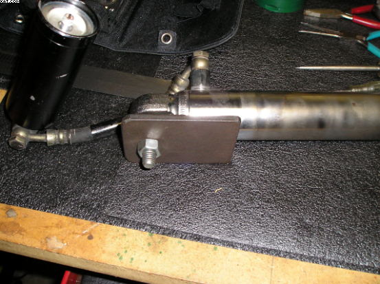
Note the schrader valve at the end of the resi..
1. Install lock plate on bottom of the shock, ( you will clamp on this )
2. Remove cap and release the gas charge Ben lists it as 185 psi,
3. Place shock in vice rod end up
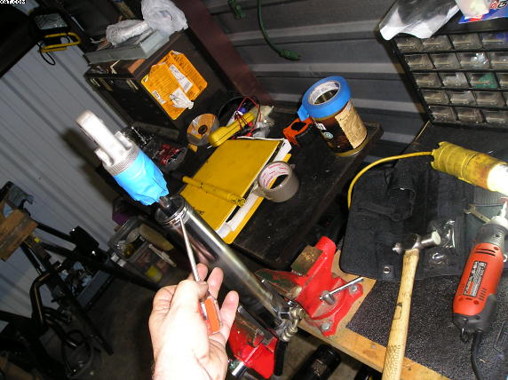
4. I used a small hobby grinder and ground 2 flats under the pressed in cap
grinding slots in the shock body, the slots are about 3/32 wide x ¼” long on
opposite sides of the body
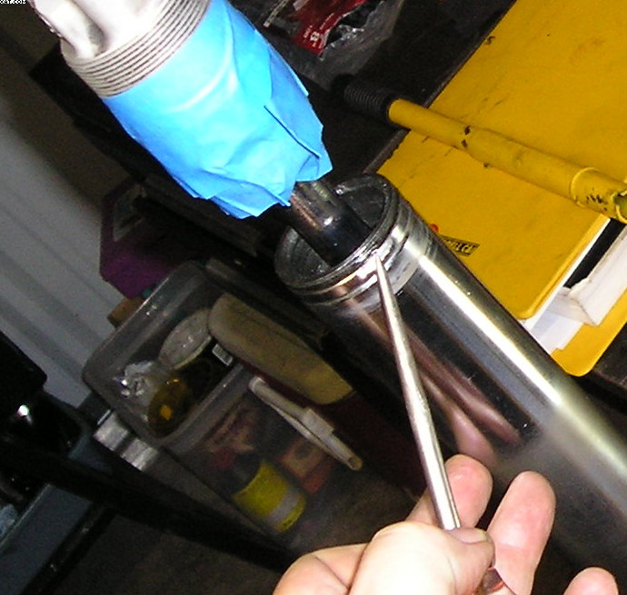
5. using a small PIN Punch I drove the cup out of the shock body
6. secure the cup and bumper out of your way tape works ok here
7. I removed the shock side banjo bolt after marking it for position watch the washers and make a mark to get it back in position
8. drain shock and remote res
9. using 3 small picks catch the top ring on the seal head ( marked SH #1)
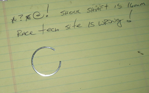
10. take a small punch and small hammer and tap the seal head on the ridge it will move down into the body try to hit the aluminum seal carrier in one place it will move as only an oring holds it up
11. take 2 picks and remove the larger ring ( marked SH#2 )
12. take 2 picks and remove the thinner ring ( marked SH#3 )
13. pull damper rod assembly out
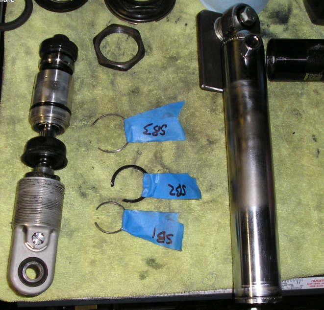
Hint on removing the rings External rings, get one end out of the grove and pull it out with needle nose pliers, Internal rings ( seal head ) pick the ring out of its slot all of the way either above or below push up or down on part of the ring to tip it in the tube this makes the ring tip where you can catch it with needle nose pliers or pick it the rest of the way out some times using 3 picks works, one pins one end of the ring, the other pulls it out of the groove a third may get in the gap between the part and the ring. To help work it out of its grove. |
    
Oldog
| | Posted on Friday, May 01, 2009 - 06:02 pm: | 


|
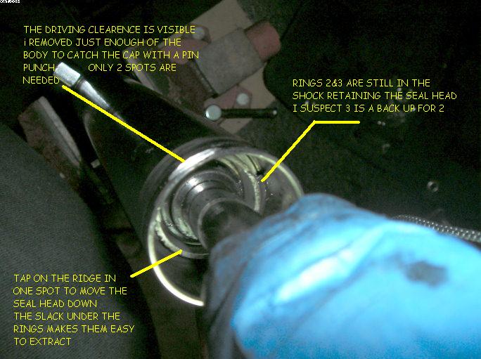
Here is a look in to the end of the shock as I am removing the rings ring 1 is out 2 is visible and 3 is just below it.
|
    
Gowindward
| | Posted on Monday, May 04, 2009 - 10:29 am: | 


|
 Jim, Huge thanks for sharing and adding the additional photos an information. Jim, Huge thanks for sharing and adding the additional photos an information. |
    
Crazyman54783
| | Posted on Monday, May 04, 2009 - 01:02 pm: | 


|
Do you know the part #'s that you ordered from motopro? |
    
Oldog
| | Posted on Thursday, May 07, 2009 - 05:51 pm: | 


|
C-man
John did not mention part nos just sizes,
in his experience he said that he has seen only one showa 16 mm seal head.
I plan on tackling the re-assembley this weekend |
    
Oldog
| | Posted on Thursday, May 07, 2009 - 06:27 pm: | 


|
Checking the seal head and bushings,
There is more information under each operation below please read first
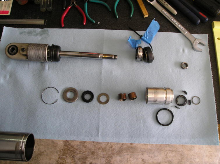
1. Remove Piston Nut
2. Remove and preserve stacking order of valve assembly
3. Remove seal head
4. From the seal head remove the dust shield
5. From the opposite end of the seal head remove the wire ring
6. Remove the washer ( thick )
7. Remove the seal groove is facing you
8. Remove the thin washer
9. to remove the bushings
Removing the piston nut.
I was told that grinding the nut face and some of the thread on the shaft was how to get the nut off of the shaft,
I used a mini cutoff wheel on a “Dremel” tool, grinding the nut and a little of the shaft threads until the nut could be removed,
the nut is 17 mm.
I was warned, Just as Ben M2 points out that there are parts that are staked into the shaft and care must be exercised to avoid dislodging or damaging them.
Setting the Piston aside so as not to mix up the parts
Once the nut was off
I took a screw driver and slid the entire valving assembly off of the rod on to the driver,
Then took a tywrap and threaded it through the “train” tied it and marked it with tape for orientation.
I did not clean it with solvent but set it aside I will wipe it off with a clean towel when I reassemble it.
Removing the seal head dust seal
Slide the seal head off of the shaft unlike forks a “bullet” is not needed here
The dust seal is a “rubber over mold on a metal part” and it presses on a raised area of the seal head.
I tried a number of careful approaches to remove it,
in the end a pick and a hammer worked after some of the rubber was ripped off.
To expose the metal insert,
A lot of care needs to be exercised here as the head is aluminum and soft the steel picks mar it up good, be patient and take your time.
But destroying it seems to be the easiest way out. With the tall shoulder you will find it difficult to pull the seal out of the head by prying. |
    
Oldog
| | Posted on Thursday, May 07, 2009 - 06:44 pm: | 


|
Removing the Bushings
This is where it gets ugly! after trying to catch the bushing with my picks and having no luck with it,
I resorted to trying the rotary file in the “Dremel” to gain an edge to tap against
the bushings which are pressed into the head and locate on a shoulder.
I notched the rim to gain access.
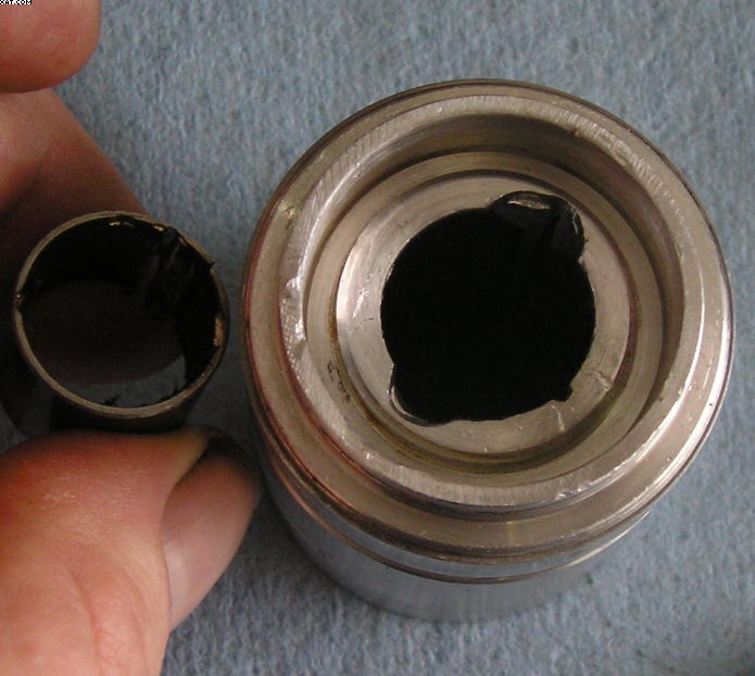
This was not successful I tried a trick that I use to remove rings from bores.
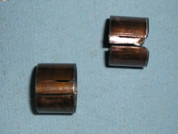
Using a hack saw cut partially through the ring just before you break through the ring weakens enough that it usually can be forced out,
while you may nick the bore you usually don’t compromise it enough to cause problems.
The bottom one caught the saw blade just as the lower edge broke out, the upper one was more trouble again the saw worked best, and a narrow slit is cut in the shoulder,
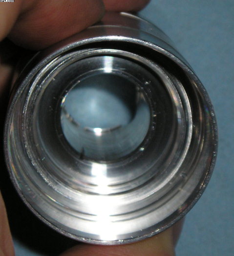
that should be no trouble, Vs the big round notches I made with the Dremel in the other end.
Again take your time cut a couple of strokes and check to see that you have not broken through. then cut some more.
If I did the notch would not be in the aluminum part, as I see it the part is still ok
( some guy at showa is reading this and sobbing [ or cursing ])
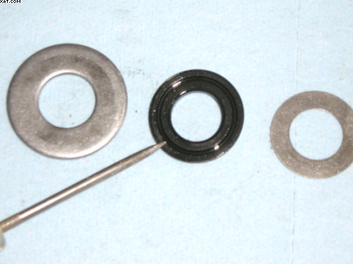
This is the inner seal as you look in the inner end of the seal head you pull the clip and the thick washer this groove is looking at you. |
    
Oldog
| | Posted on Thursday, May 07, 2009 - 06:51 pm: | 


|
parts and oil are in hand
I expect to try to rebuild the damper this week end or next week stay tuned. |
    
Benm2
| | Posted on Saturday, May 09, 2009 - 08:38 am: | 


|
Been a while since I've had any spare time! Anyway, here's the information I have about the stock M2 recall shock spring:
1. overall length 9", 50mm ID spring.
2. Stock spring is progressively wound. I measured the rate on a friend's rate tester:
1" deflection - 343 lbs/in
2" deflection - 365 lbs/in
3" deflection - 401 lbs/in
3. The stock wire diameter is 0.425", and I calculated a 4.14" stacked height, for about 4.86" of available spring travel.
4. I measured the shock details and arrived at a maximum installed spring length around 8". This was tough to measure with the tools I had available, so it is an approximation. It means the shock at minimum preload compresses the spring 1". |
    
Benm2
| | Posted on Saturday, May 09, 2009 - 11:16 am: | 


|
I guessed the bike weighs about 420 (mine's track only) and had about a 50/50 weight split, putting 210 on the rear wheel with no rider.
Assuming a 2:1 leverage ratio, a 210 lb weight gets magnified to 420 at the spring, so the bike with minimum preload JUST about holds up the bike. What that means is tbe rear suspension is close to "topping out" (fully extended) with no rider on it.
I targeted the same ride height at minimum preload, so I would need 350lbs of spring push at an installed length of 8", the minimum preload setting.
I pulled my spring number from a couple of things:
1. Data I found on Badweb that indicated earlier WP shocks had a spring close to 500lb/in, and that it generally was good enough (or even a little too stiff) for racing use.
2. The 500 lb/in spring seems a popular option for the Works & Penske shocks.
3. Traxxion Dynamics has a spring rate chart that lists the reccomended spring for the Buell X1 at 475 lb/in.
I was getting tired of dragging the bellypan on the ground mid-corner (had it lever the rear tire once) while running maxed preload, so I went a bit stiffer to 500 lb/in.
I needed the spring to give 350lbs at 8" long. If I compress a 500lb/in spring with 350 lbs, it moves 0.5". So, I got a spring with an 8.5" free length.
Because my spring was straight wound, I ended up with just under 4" of available travel, and a 4.1" stacked height. The stacked height was practically identical to the stock spring, so I shouldn't run into any coil bind issues.
With the spring on the bike now, its just about topped out with me off the bike at minimum preload. I only had to put in about 2 turns on the adjuster to get my static rear deflection at about 1", close to the reccomended rear "race sag" given by Race Tech.
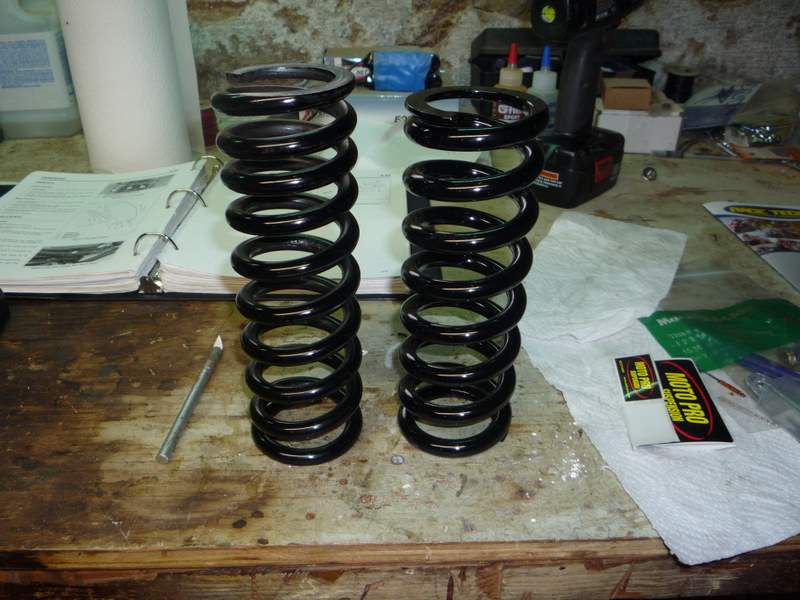
Also, the spring was made by MotoPro, same guys who have the correct 16mm sleeves & seals, and the good customer service. John got me the spring in about 3 weeks. The new spring is on the right in the picture below.
|
    
Benm2
| | Posted on Saturday, May 09, 2009 - 11:35 am: | 


|
Once you've made it back to re-assembly, note the following info:
1. Make sure you use a new shock nut to retain the piston. They are available from RaceTech & MotoPro. It is an M12 x 1.25 nut, you probably wont find one at Home Depot...
2. Make sure you use RED loctite to hold the nut on. Loctite works best when the surfaces are clean & oil free, so I spray the threads on both the nut & rod with brake cleaner before I put the loctite on.
3. Make sure you use a torque wrench to reattach the nut. My RaceTech instructions say to torque the nut to 25 ft-lbs.
Now on to the next challenge, refilling the shock & reservoir.
SOME INTERMEDIATE NOTES:
For those of you brave enough to install a Gold Valve kit:
THERE ONLY SEEM TO BE ONE OR TWO FOLKS AT RACE TECH FAMILIAR WITH THIS SHOCK. I spend a lot of time on the phone trying to get valving information for the shock, but finally got it straightened out. The actual stacks they give you will vary per person, use and setup, so its important to get the information at hand before you call. Also make sure you tell them you have the post 2000 X1 shock, which is the recall Showa, since they don't really cross reference it to other bikes. (NOTE I don't know if the X1 is the same spring rate at the M2!).
Another note about the Gold Valves: On a "regular" shock, the compression valving is setup so as you push the piston assembly back into the shock body, it is the valving that deflects to let the oil past the piston. Why is this important? Because the compression valving stack is ALOT softer than the rebound stack. So on a regular shock, a firm thrust downward with the piston will open up the compression valve & let air bubbles past the washers.
On the pull shock, the rebound stack ends up on top and is much harder to push open. In fact, I could NOT get the washers to open no matter how much force I used to move the piston. I found a way around it, but wasn't happy about doing what I did. I'll describe it more later.
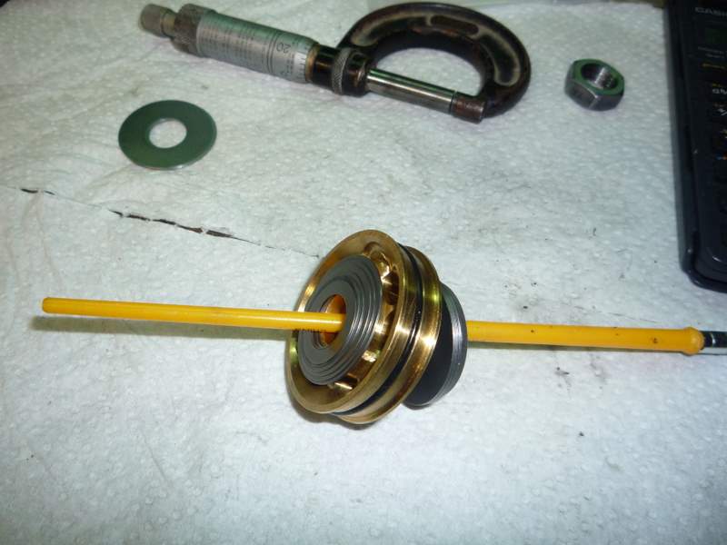
Here's a quick shot of my Gold Valve before installation:
|
    
Court
| | Posted on Saturday, May 09, 2009 - 01:06 pm: | 


|
I don't care if I EVER rebuild a shock . . this is the best reading in years!
 |
    
Benm2
| | Posted on Saturday, May 09, 2009 - 06:40 pm: | 


|
Thanks Court!
Onto the refill! What happens here depends on how far you took the disassembly, but the assumed starting point is:
1. Seal head rebuilt & put back on shaft, along with any parts that go above it.
2. Compression valve put in place.
3. Valving stack installed.
4. Nut on & torqued.
** If you've used the RaceTech valve, then be sure to read their directions carefully regarding arrangment of extra shims to get the nut to torque properly. Their included video is decent too. **
If you used a Gold Valve, it will look like this:

If you rebuilt with a stock piston, it will look like this (NOTE PICTURE SHAMELESSLY STOLEN FROM OLDOGS POST ABOVE):

(Message edited by benm2 on May 09, 2009) |
    
Benm2
| | Posted on Saturday, May 09, 2009 - 06:57 pm: | 


|
The next thing to do is re-attach the reservoir to the shock. Use new copper washers. Copper work-hardens pretty easily and re-used ones won't be as soft & might not seal as well. Since they come in a lot of similar sizes, bring one with you to the autoparts store to be sure you've got the right size.
Barring actual data from Showa on re-assembly, I used the same torque spec as the brake caliper banjo bolts: 16-20 ft lbs in my 2000 M2 manual.
The bladder should NOT be back in the reservoir at this point!
Now setup the shock body & the reservoir so that they are both vertical, open ends facing up. During this process, make sure that the rebound adjuster screw on the reservoir is backed all the way out. I clamped my reservoir with a wooden screw clamp, then clamped that to the top of the vice. I held the shock body in the vice by the lower eye.
Yes, I wasn't bright enough to take pictures here. Hopefully Oldog will do a better documentation job than me & add more detail.
**** NOTES - bleeding the air out of this shock is difficult. I still don't know if I really got mine done right, and I used almost two quarts of suspension fluid trying to make myself happy with the job. I don't know if its easier with the stock valving ***** |
    
Benm2
| | Posted on Saturday, May 09, 2009 - 09:16 pm: | 


|
Here's an image that represents the reservoir cap:
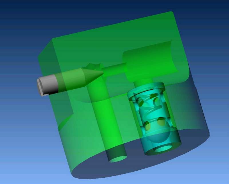
The oil flows in from the right side when the shock rod is pushing into the housing body (the rebound stroke on the pull shock). Both holes on the bottom connect to the pressurized area of the bladder housing.
During rebound, the oil flows past the rebound needle which controls the flow rate. Note that MOST of the suspension oil will go thru the shock piston, but since the rod is going INTO the shock body, it has to displace some oil into the reservoir. That flow (however small) is the control circuit for low speed rebound.
During compression (extension of the shock) the oil will go thru the check valve on the right side, bypassing the needle valve. This keeps the adjustment of the needle valve from affecting the compression damping at the same time.
Why are these important in the re-assembly context? THEY ARE ALL FULL OF AIR.
When you pour oil into the reservoir, it might make it to the hose, and across into the shock body. It probably WONT get the air out of the check valve, as a gravity fill wont move the check valve spring.
So, here's what I did: I put oil into both the reservoir & shock body with them in the vice, filling the reservoir about 75% of the way. Then I waited about 1/2 hour to let any static bubbles work their way out.
NOTE I SETUP THE RESEROIR, BODY, AND HOSE SO THAT BUBBLES WOULD FLOW FROM THE RESERVOIR UP TO THE SHOCK BODY THROUGH THE HOSE.
Then I took the bladder & squeezed a bit more air out of it, so it was slightly collapsed. Then I inserted it into the reservoir. This WILL make a mess if you're doing it right, as it should overflow with oil as part of eliminating air from the system. Then I put the snap ring in, and put about 10psi in the bladder. That pushes oil through the hose into the body.
Then I released the bladder pressure, removed the snap ring & bladder, then repeated the above about 3 times. After the fourth time, I left the 10psi in the bladder for the next part. |
    
Oldog
| | Posted on Monday, May 11, 2009 - 09:36 am: | 


|
Wow!
I have been thinking about filling from the bladder end I have used about 350cc of fluid (including floor oil) I am sure that I have put the reseviour on backwards
heres my version..
Section 3
RE ASSEMBLEY
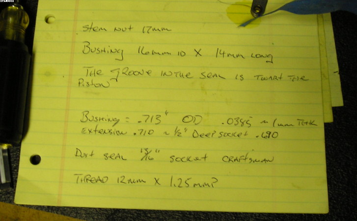
The bushings are not available as 14 mm units, use a 15 mm and a 12 mm leaving a 1 mm gap between the bushings. I believe that bushing wear is part of the cause for shaft seal failure as the shaft can rock in the seal
1. Secure the shock shaft ( by the eye end ) In a vice.
2. Press the bushings in to the head
3. Press the dust seal on to the eye end of the head
4. Fit the washer(thin) seal(groove out), washer (thick), and keeper to the piston end.
5. Lubricate the seals ,bushings, and shaft with clean shock fluid.
6. Work the seal head on to the shaft be careful not to damage the seals on the shoulder
7. Place the piston & valve stack on a screw driver orient them correctly for install, cut and remove the tie wrap
8. Holding the stack, place the driver against the shaft end and slip the parts on the shaft.
9. Clean the threads then apply RED LOCTITE install the nut tighten
GOOD and TIGHT John at Moto Pro said tight as much as 60 ftlb but no specs exist
10 Remove the assembly from the vice and set it aside
11 Place the body ( with plate attached ) in the vice mouth up
12 Lubricate the piston with shock oil and install in body
13 lubricate the seal head oring and sides and push into the body
14 press the head in past the inner grove fit #3 ring to body
15 fit #2 ring into grove as evenly as possible
16 pull the shock eye out ( moving the seal head out and trapping the rings, watch the position of #2 ring
17 Fit the #1 ring to the seal head [ this traps the other 2 rings in the grove ]
18 tip the body assembly so the open fitting is the high point
19 stroke the shock, checking for binding leave the rod fully extended
20 fill the shock body with fresh oil
21 stroke the shock slowly to work the air out plugging with the thumb will work a few strokes will work the air out of the shock.
22 open the reservoir by removing the clip and bladder,
23 while holding the hose up fill the reservoir about 1/3 full of shock fluid
24 Lower the hose and allow a small amount to run out,
25 Remove the schrader valve from the bladder and set it aside
26 compress the bladder and fit it to the reservoir
27 secure it with a clip
28 fit and assemble the hose and banjo to the shock
29 stroke the shock and check for leaks
30 refit the valve
31 charge with gas
32 refit the cap on the Schrader valve
33 the shock is ready for the spring. |
    
Oldog
| | Posted on Monday, May 11, 2009 - 10:08 am: | 


|
The Bushings are about .713” Dia when fitted to the head, use a c-clamp or any other handy pressing instrument. I used a ½” [3/8 drive] socket, and then a 3/8” extension bar both were just smaller than the head bore ( by .003” ) If you miss this you will mess up the aluminum head. I used my drill press as a press to push the bushings seals on the head this is not a good item to pound on.
I left a gap between the bushings
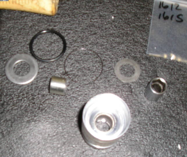
the dust seal pushed on with a 13/16” socket it clicks into place
I tried tape on the shaft shoulder it just made a mess and required a disassembly to clean residue from the shaft and head. gently press and twist once past the dust seal its easy,
removing the spring on the dust seal helps just remember to refit it when the head is installed
Clean the shaft threads with brake clean, check the fit of the nut, the male threads on the shaft were messed up so a massage on the bench grinder to clean the lead thread was needed the nut should start and turn on easily
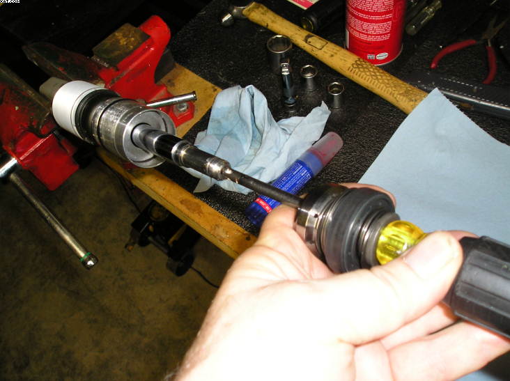
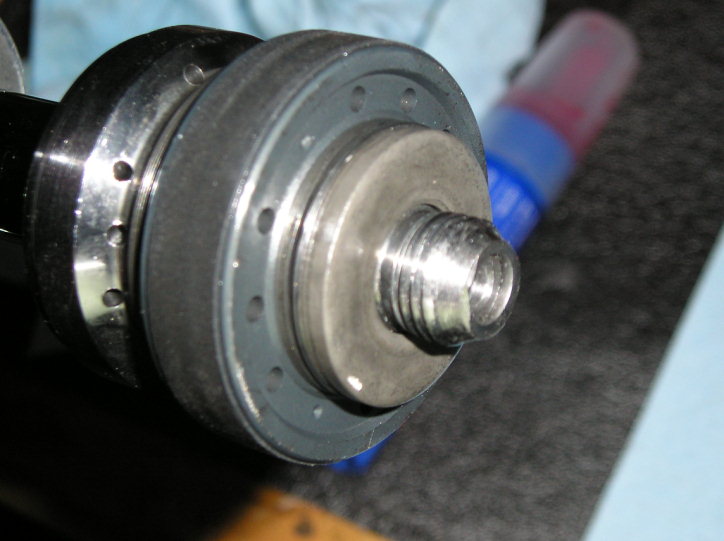
with the piston assembly in place prior to install of loctite and nut, check that the stack is beyond the shoulder of the shaft and not flush or below THE NUT MUST CLAMP THE PISTON ASSEMBLY IF NOT A FAILURE WILL RESULT.
on reassembly of the hose banjo bolt check not only direction but up and down for orientation as there is a top and bottom. as well as rotational position,
the fill and assembly of the shock is an attempt to preclude air from the oil.
I worked the piston back and forth several times to purge the air out.
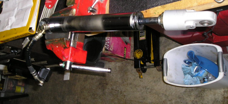
|
    
Crazyman54783
| | Posted on Wednesday, May 13, 2009 - 12:49 pm: | 


|
got mine back together last night just waiting on picking up the oil tonight. thanks you guys for your help. |
    
Oldog
| | Posted on Tuesday, June 09, 2009 - 10:24 am: | 


|
ALTERATION to assembley:
30 Open reservoir by removing ring and bladder,
fill the body partially and stroke shock till oil comes out of orifice clear with no entrained air
31 fill the reservoir about ½ full
32 Collapse bladder and re install do not pressurize at this point there should be a
small amount of oil seeping as the bladder goes home, oil fill is about 350cc
IF the fill is right the reservoir end will be pushed against its retaining ring and you cant push it in you can rotate it. |
    
Oldog
| | Posted on Tuesday, June 09, 2009 - 10:42 am: | 


|
Section 4
Assembly of the spring to the can
put locking plate on shock and secure rod end up in a vice
1. Wiper into can
2. Outer sleeve into the can
3. Inner sleeve into spring
4. Spring and sleeve into the outer sleeve, check wiper
5. Spring seat radius is up and bears on the clip
6. place this over the shock body
7. place the shock into the press set it against the locking plate fitting in the opening
8. place the pipe sleeve over eye end
9. set and square up press plate
10. finger tighten nuts
11. press spring keeper and spring down and over shock body
12. fit locking ring (wire. [over body] in the mouth of the pressing tool )
13. loosen press plate slightly to catch wire in collar ( radiused side up on the collar )
14. remove lock plate
15. loosen press plate spring can will rest against the hose fitting on the side of the body
16. install the nut plate and screw on it till it stops push the moving eye end down and fit this in the spring can.
17. fit press plate and tool
18. press down and fit last lock ring the spring is assembled
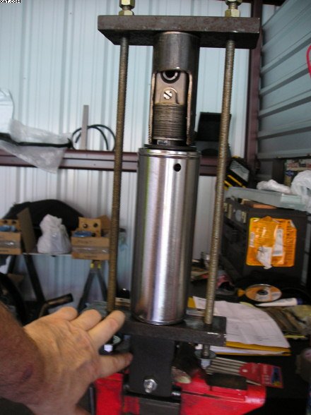
the internal spring collar, the wire ring should be checked and made sure that it snaps on the shock body and stays in its grove, putting it in place is a bit of a challenge
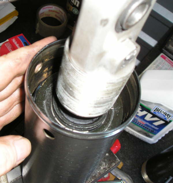
( this wire ring retains the spring on the shock body! )
I tried to assemble the shock on the lock plate and I could not line the plate and the can up to fit them, also the pressure that the spring exerts on the fitting is not much so its not as much of a concern as I initially thought it might be,
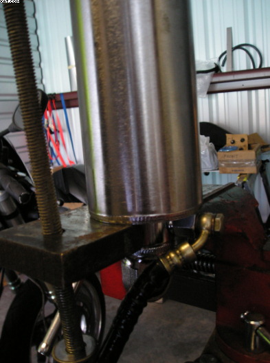
I pressurized the shock with compressed air, the hose end of the reservoir would turn before I did this, not after ward.
I will have to seek out a shop to fill it with nitrogen the shop needs a controls connect release device for this.
I hope that this helps with seal replacement and oil change.
I will set the ride height soon and the tools will be available to borrow.
Note I made a revision on the assembley,
the shock can be purged of air by removing the bladder end of the reserviour and working the shock until the oil fills and empties the resi body with no bubbles you will want to tip the fitting up so its the high point, again fill the resi about 1/2 full and squeeze the bladder some, re assemble and after spring install re charge, compressed air is probably OK as the bladder seprates it from the oil, and as hard as you may try you will have a little air in the oil. |
    
Oldog
| | Posted on Monday, March 08, 2010 - 12:24 pm: | 


|
BUMP |
    
Two_seasons
| | Posted on Sunday, May 29, 2011 - 10:06 pm: | 


|
Bump again for excellent information.
Thanks guys for your knowledge and the pictures are helpful too. |
|