| Author | Message | ||
Gowindward |
Yes, I think your load numbers are conservative. Add in dynamic loading and well no wonder they fail if the Barry spec sheets are close to reflecting our parts. | ||
Oldog |
S-Eric I am not sure AL [American Sport Bike], Court, or FMJ may Know I think that is a no on the rear isolator | ||
Oldog |
Hey Loren post up the dimmentions I wanna look and see what may fit and compare for load. | ||
Sloppy |
I can't help but think that if some people are getting thousands of miles from their iso's and others are only getting a few hundred, and "if" they're all the same iso, then why the difference in part life? A possible conclusion is that perhaps there is something else besides the front iso that is wrong... perhaps belt tension, shock, preload, rear iso's, etc. It seems that when the bikes are new, that the front iso lasts for a long time, but after time when the front iso get replaced, they don't last very long. Perhaps another part is wearing out and putting more stress on the front iso? Iso failure could be an effect, not the cause. Helpful? Don't know, but wanted to share a different perspective. | ||
Gowindward |
Jim, here are the measurements off the OEM part. 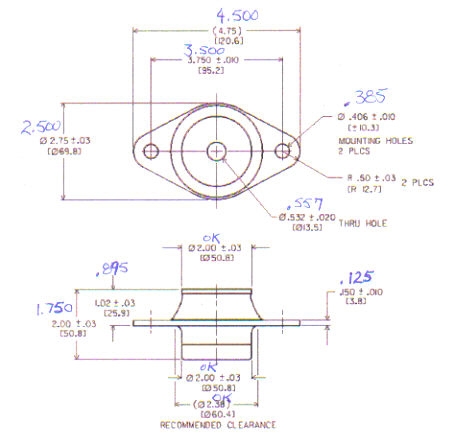 | ||
Oldog |
More Data: Dave from LORD sent me the data for the # listed related to the Drag spec part Here are some .tif files of the drawings. Hopefully you will be able to read these better than the .pdf files I sent yesterday. The J-21920 series mounts have a 11.66 mm (.459 inch) diameter center hole that will accept a 7/16 bolt and (2) 10.31 mm (.406 inch) diameter holes in the flange that will accept 3/8 bolts. Here is a breakdown of the mount characteristics: J-21920-1 Rubber: 40 durometer natural rubber Axial rated load: 849 N (190 lbs) Axial spring rate: 210 N/mm (1,200 lbs/inch) Radial spring rate: 225 N/mm (1,285 lbs/inch) J-21920-3 Rubber: 45 durometer natural rubber Axial rated load: 1,169 N (263 lbs) Axial spring rate: 288 N/mm (1,645 lbs/inch) Radial spring rate: 301 N/mm (1,719 lbs/inch) J-21920-4 Rubber: 50 durometer natural rubber Axial rated load: 1,368 N (308 lbs) Axial spring rate: 337 N/mm (1,925 lbs/inch) Radial spring rate: 354 N/mm (2,019 lbs/inch) }I can't help but think that if some people are getting thousands of miles from their iso's and others are only getting a few hundred, and "if" they're all the same iso, then why the difference in part life? A possible conclusion is that perhaps there is something else besides the front iso that is wrong... perhaps belt tension, shock, preload, rear iso's, etc. I Agree with you on this, what are the possible loads that are applied to the front iso. What are the likely parts that can fail and cause this problem? parts for the mounting system A. Front Isolator Failing [ rubber rips ] B. Alignment Tie Bars Loose attach, worn joint, loose connecting stud C. Rear Isolators Broken Bond, loose bolts, out of position. D. Rear Engine Monnt Loose Bolts, broken, E. Bearing Bolts (isos bolt to this) loose F. Front Hanger Bracket cracked & flexing, loose mounting bolts G. Front Cylinder Head broken bolt or casting.} | ||
Oldog |
Possible stress risers Tight belt? High Preload for suspension Overload due to Stunts Overload due to exceeding Gross Weight Overload due to impacts Overload due to wear of other parts Overload due to mis adjustment / alignment The basic mounting system is 3 points on rubber, 1 the front. and 2 at the rear. These form a triangle as viewed from the top. In addition to these there are several tie bars which are bars with heim joints built into the ends. ON the X1 there are 4 that I can find, 1. by oil filter mount 2. on head bracket by front isolator 3. on top of the motor between the heads 4. at the rear of the engine mount block these tie bars and the isolators connect the frame and the motor / rear suspension together. If I understand how this works ( normaly ) loads imposed by engine vibration are dampened by the rubber parts the tie bars allow movement in one plane [ uniplanar ] this would be in the vertical plane as viewed from the side. Radial movement is also permitted in this plane, twisting or lateral movement is restrained by the bars and the rubber mounts. The purpose is to keep the wheels in alignement for operation yet damp and control vibration for comfortable operation. Forces: Static at rest laden 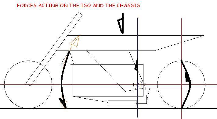 | ||
Buellistic |
Sloppy: "i" have found that IMPROPER INSTALLATION is the cause of a lot of FAILURES on a lot of things on a BUELL !!! | ||
Natexlh1000 |
I tend to agree with Buellistic on this. Perhaps one of those heim joint turnbuckle things are messed up, allowing extra lateral play? | ||
Oldog |
\blue {"i" have found that IMPROPER INSTALLATION is the cause of a lot of FAILURES} Cant Disagree please review and comment here. http://www.badweatherbikers.com/cgibin/discus/show .cgi?tpc=3842&post=1215915#POST1215915 My procedural post and updates in the KV} | ||
Buellistic |
Oldog: Not "DISAGREE'ing" with you !!! Most of the MECHANIC'ing stuff we know is not in the FSM's and from years of of being OLD ... Like the OLD MECHANIC told me when being trained, we can tune two same engines "BUT" until you have paid your dues mine will always be better(last longer and be faster) !!! (Message edited by buellistic on March 11, 2009) | ||
S2pengy |
One thing you may want to look in to; length of steel tube and placement in the rubber. If too much of the steel tube is sticking up the washer is going to try to push the steel tube through the rubber tearing it at the bottom ..... Sound familiar????? Last one I installed I cut down the steel tube on a lathe to provide .040" clearance with no load between washer and rubber.... | ||
Buffalobolt |
S2pengy, I did the exact same thing! I also thought that that the tube was too long and causing the rubber to tear under load. I was explaining this to another Bueller, and when I went to show him what I did on mine... D@MN!! Torn again!! | ||
Natexlh1000 |
Interesting! My newest isolator seemed to have a lot of clearance between the "D" washer and the rubber underneath it. I thought I was just imagining things by comparing it to the old one. Perhaps this new one won't last as long as I anticipated! | ||
Oldog |
I go back to what I said earlier, either bad isos, tie bar issue, "crap parts" [ bad or wrong parts ] the Isolator should with stand loads up to the load imposed by the system at max gross I am replacing rear isos, swing arm "bolts" checking the tie bars, and the front iso before its ridden again. | ||
Oldog |
Nate The top washer is a limiter / safety device if the bond fails and the isolator drops the d washer catches on the head side and rubber to provide "failsafe" protection. It may also provide a limit of travel in the down ward direction, like when you hit a bump OR the front wheel leaves the ground under hard acceleration. [ not to mention the ocasional hooligan outburst =) ] I initialy wondered if you trapped the elastic between 2 large washers and compressed it would that help. From what I can find out, not likely it may cause it to fail. the Urethane iso that Al has mentioned is the Velva ride they also make tie bars with urethane snubbers in them for harley apps that may work good, for a Buell I cant see why it would do any thing but cause handling / reliability problems. Did you ever have the factory rear Isos changed? I have sit an searched most of the day [ its too slow here at work, =( ] and looked at the sketch of the bike and wondered about the forces acting on the rubber mounts... Come on Friday.. (Message edited by oldog on March 11, 2009) | ||
Dave_02_1200 |
Has anyone used the Velva Ride #CC30130 replacement for the OEM #16207 79B? I wonder if they might last longer. Dave | ||
Oldog |
Not accorfing to AL Urethane isos fail in short order, | ||
Gowindward |
Here is what I'm thinking. An aluminum bar 3/8" x 2" replacing the D washer with two 90 lb load rated bumpers outboard the isolator set at a height as to be overload stops. I have the parts, just need to find the time to prototype to see if I can fit it into the space in the frame. It would give 180 lbs of additional support in an overload condition, but not reduce the vibration reducing of the stock isolator.  | ||
Natexlh1000 |
Seems like a decent idea but will that bar fit inside the neck area? I seem to recall that it was pretty tight in there. | ||
Sportyeric |
And leave room to get a box-end wrench over the nut! | ||
Jramsey |
Loren, very interesting idea. Jim, was able to login this AM. Have to re-enter my password every session. Will try the edit/delete. Thanks for the help. Enjoyed talking to you last evening. James edit......../delete Think I have puuter prob fixed (Message edited by Jramsey on March 12, 2009)  (Message edited by Jramsey on March 12, 2009) | ||
Gowindward |
There is plenty of room on top for the nut since the plate replaces the D washer. The plate would have a counter bore in it the size of what's used on the D washer which is 1" approx. x .188" deep. Height position of the bumpers would be adjusted by counter bores for them to hit in. The overall width of the plate would be approx. 7". My S3T has a big wire bundle that makes things tight. My S2 is pretty open in that area. I need to make a quick and dirty cardboard prototype to see if things will fit. | ||
Dave_02_1200 |
Loren, Looks like it would be a big help in the event of an isolator failure. Best of all, it will not interfere with normal function of the isolator. Keep us posted on your progress with this idea. Thanks, Dave | ||
Oldog |
Well the "Brown truck" delivered the basis for a weekend on my knees, the DS#243515 isolator is made in Tiwan, and the rubber seems harder than what I remember for the Buell packaged unit. With it came the 2 rear isolators with SOCKET SCREWS {TORX SUCK} ( you want to buy the kit from AL getting the left and right with the CORRECT BOLTS ) As expected, the temps have dropped from the 70's to the 40's  | ||
Gowindward |
 Yippee the brown truck! Yippee the brown truck! Hold on he's at your house and not mine.  I'm forever waiting for the brown truck to show up with something. That may be a good thing having the rubber being a harder durometer should give it more shear strength. I have a pair of those on order and waiting and waiting for the brown truck. | ||
Jramsey |
Jim, my rear isos arrived yesterday evening about 5:15. Got started 6:00 and finished up about 7:30. While I had it on the lift I flipped the -79D right side up.It shows no signs of wear or tearing for being usd for 1,500 miles. Now rocking the bike on the side stand shows virtually no movement and the rear head pipe to frame clearance is about 1/4". | ||
Sleez |
just found this in the JP catalog; 2009 pg 522. http://www.jpcycles.com/Search/ProductDetail?sku=431-385&N=2761610%202761612%2028002076%2028002146&Ne=72635&Ntk=All&Ntt=&Ns=image description; � Finish: Polished� Material: Billet Aluminum� Sold in Units: Each� Brand: Hotop Designs�� Made in the USA: 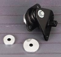 fitment; 1995 - 1996 Thunderbolt S2 1995 - 1996 Thunderbolt S2T 1996 - 2002 Lightning 1997 - 2000 Thunderbolt S3T 1997 - 2002 Cyclone 1997 - 2002 Thunderbolt S3 1998 White Lightning from the catalog; "2-piece billet aluminum disc kit restricts excessive movement of the engine in the motorcycle frame. Especially useful for big inch motors. Installs with OEM hardware. Note; motor mount and bracket not included." no experience, or idea if it works at all???? | ||
Oldog |
J Ramsey and I have changed them out on our bikes, he did Naustins old S3 and I did my X1 front and rear isos. My hands are sore, I plan on posting up this evening if possible, I have the last 2 isolators that I purchased from Buell MC they are both noticeably softer than the DS part WAAAAAY softer, both have failed catastrophicly stay tuned for a full report.. | ||
Oldog |
This is an account of my actions relating to premature front isolator failure on my X1 the isolator holds the front of the motor in the frame In order to be thorough in the examination of the problem, I decided to replace the rear isolators a year early, The swing arm bolts (plugs) were corroded and tracked up they were replaced as well. The failed front isolator was replaced at this time Date 3-14-09 mileage : ~ 387xx The Failed front isolator.  This part failed with less than 6 months of service, I noticed odd vibrations at times while riding BEFORE the failure, from what I have been able to learn about these types of mounts the different hardness and sizes control load rating and frequency that they handle the Barry mounts are made either of Neoprene, or Natural rubber. The mounts can be subjected to up and down loads and side to side loads. The photo above is a catastrophic failure in progress. As the mount fails it can allow the front lower tie bar to strike the oil filter this is evidence of excessive movement.  I took the above as I started the process of prepping for rear tear down of the rear end. the process requires you to remove one end of three of the four tie bars. |