| Author | Message | ||
99savage |
Small problem w/ 06 Uly but before commencing to ripping things apart in a 20°F, unlit barn thought would ask advice. *Right turn signal does not work if forks turned right. *Works fine when turned left *Centered - sometime yes & sometimes no. ***Suggests loose wire. Tugging on the wire where it goes into the signal has no effect. What should be torn off 1st?? Thanks | ||
Ft_bstrd |
Check the wiring harness on the left side of the bike where it leads into the front fairing (large black bundle). The 06's are known to have potential chaffing problems there. (Message edited by ft_bstrd on February 28, 2009) | ||
Glenn |
You probably have a broken wire at the cold fusion crimp located approximately where the plastic shield leaves the frame rail. The same thing happened to me on my '07 and in the process of first checking at the right turn signal light and then tracing the wiring harness back by pushing and pulling I found the intermittent connection problem in this location. It seems like the cold crimp that Buell has used isn't properly located to avoid bending fatigue in the wiring. The connection is otherwise sealed real well but the back and forth movement of the steering breaks the wires. I've attached a few shots that I took when I found and repaired mine by soldering. don't use too much heat and double heat shrink tube it or it may break again.  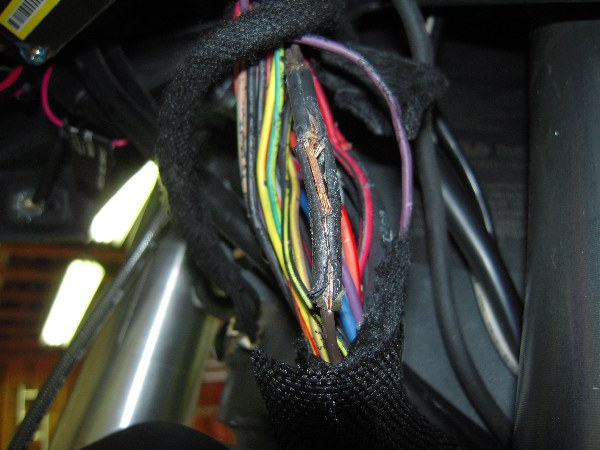 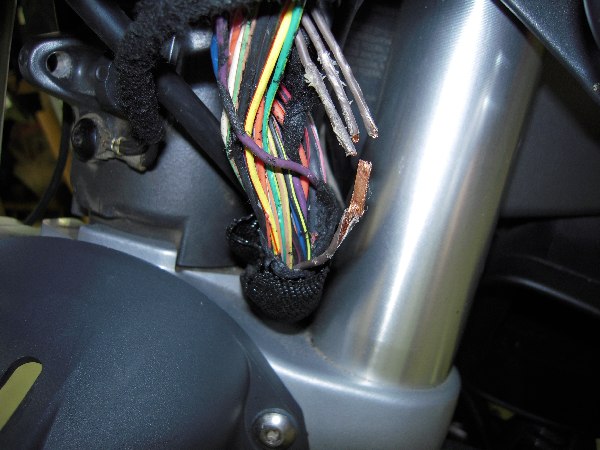 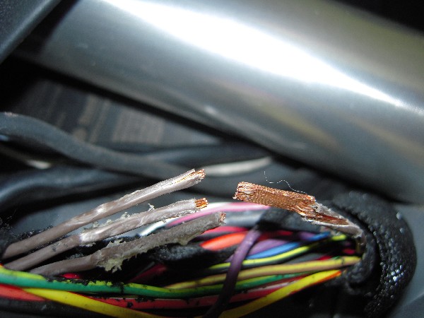 Glenn | ||
Etennuly |
Mine had the same problem when it was a year old. After soldering the wires I just pulled the whole harness down about a half inch in the clamp on the steering head. Still going at nearly three years old. | ||
Rays |
I had the identical problem on my '06. There is also a similar join for the power wire (red wires) where it splits off the back-up power for the instrument cluster and on the '06's it is also located right on the bend where the loom flexes. Also be wary of the four ground connections in the background of photo #3. I have had all four break at various times on mine. They provide ground to : - Blinker relay - Horn - Headlights - Front Aux Power connector On the circuit diagram they are identified as Gnd 4 and Gnd 5. | ||
Xbimmer |
Get rid of this thing if you still have it: 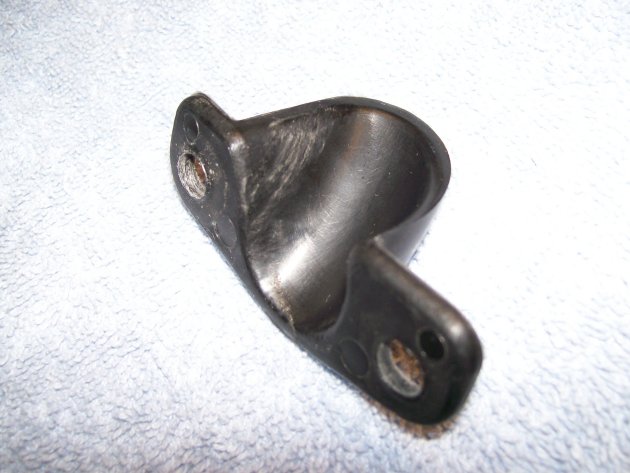 It's the old style guide which bolts to the steering head on the left and crams the throttle cables and harness bundle into an impossibly small space. My tach was working erratically, turned out the wire within the harness at that guide exit point had broken WITHIN the insulation, not visible from the outside. I bought the updated part #Y1000.2AK but haven't yet installed it. I loosely ziptied the harness to the bolt holes at the steering head so it can move freely with some restraint, works great and the steering inputs are finally even left and right. | ||
Ronmold |
Just got my notice today, '08 + KLR650 have a recall for the main wire harness. Too many reports of chaffing & shorts and in several areas. I'll bring mine in for inspection so Kaw quits pestering me but I really don't want some jr. wrench tearing my harness out, especially after all the electrical mods I've done. I think my bike is OK though. (other than it needs another cylinder!) | ||
Blk_uly |
i had the exact same problem you describe to the letter! The problem turned out to be a bad ground connection on the steering neck one of the several ground loops was crimped through the insulation. Mine is an 08 but this may or may not make a difference but it's definatly worth a look. Good luck & please keep us updated and then post this to this knowledge vault if you can. | ||
99savage |
Thanks! Problem definitely in wire bundle like you said. Can't see it even w/ the windscreen off but tugging on wires causes the problem. Do I have to remove the lower "Front Module" (sec's 2-27 to 2-29 in manual) to get enough access to repair it? Stupid question - Embarrassed - Removing the headlight ass'y allows removal of the loom. Had to quit for the day - hands too cold - no light. - THANKS ALL (Message edited by 99Savage on March 01, 2009) | ||
99savage |
Electrical guys give me an opinion: How about using crimp-on, male/female connectors instead of soldering? Could then heat shrink the completed joint. Hands not real good @fine work It is impossible to get under there Worry about cooking the other wires Also, how did you re-sheath the wire bundle after you repaired the joint? Thanks | ||
Darthane |
Crimp-ons are generally pretty crappy. I strongly recommend you never use them as a permanent solution. Do yourself a favor and do it correctly - get a splice clip, crimp it down well, solder it, and cover it with sealed heat shrink. | ||
Etennuly |
I redid the original sheath with the help of electrical tape and a zip tie at each end. I pulled out about an additional half inch of harness before putting the plastic holder device back on. | ||
Dbird29 |
My opinion is a crimp connection would not break from vibration as soon as a solder joint. | ||
Thetable |
How about using crimp-on, male/female connectors instead of soldering? Could then heat shrink the completed joint. Skip the crimp connectors, they have always been a weak point in anything I have worked on. If you don't feel comfortable doing proper soldering, look into what is called a solder splice, or solder sleeve. Basically solder inside heat shrink, so you slide the tube over the joint, apply heat until the solder melts into the joint, and you are done. Minimal manual dexterity required. | ||
Rays |
I ride my Uly in traffic every day so I needed to get the blinkers working reliably straight away. This is what I used as a 'temporary'' solution 18 months and 32,000km ago - I've been meaning to get back to it for ages and so far it has been a very reliable fix. To join 3 wires into one isn't easy to do cleanly but by using an in-line crimp with the insulation stripped off, soldered and then covered with heatshrink it is a pretty reliable connection (I used two sizes on the single wire end to give better mechanical support given the size of the crimp). This isn't too difficult to solder (with no risk to the rest of the loom) when the wires are held this way. I also moved the multi-wire join up towards the instrument cluster by about an inch and a half with another single wire join 4 or 5 inches further down to avoid the area where the loom flexes most. 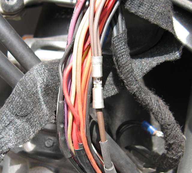 I re-used the friction tape but you can purchase this readily if you wanted to put fresh tape on. In the US McMaster-Carr have it in 0.75" and 1.5" width rolls according to their website. | ||
99savage |
Thanks for the help. Got everything together & all works. Wish I had seen Rays job before I started. Mine was so ugly felt relived when I covered it w/ the heat shrink. Still do not have the new gizmo from Schaeffer's so temp. covered everything w/ corrugated tube from Radio Shack & zip tied in place. Thanks again | ||
Tootal |
Glad all is working again. I too prefer solder and shrink wrap however if crimping is ever used do yourself a favor and put dielectric grease on the wires before crimping. Corrosion is usually worse than the crimp itself! As far as that loop, I too got rid of the plastic "holder" and just loosely wire tied it to the frame. So far, no electrical problems in this area. |