| Author | Message | ||
Skrip |
Hey guys. I have an EBR 1190 ignition that I'm trying to fit into my '08 1125R (due to breakage)but the wire colors and connector are different. Still the same number of wires (4) coming out of both and the wiring schematic on EBR's website is, for all intense and purposes, the same as my '08 but it doesn't show the colors of the wires coming from the ignition switch itself. So I suspect it would work I just need the right wires going to the old connector. Does anyone know what wires are hot going into the EBR ignition. On the old ignition I have two reds that are the hot leads. But on the EBR I have no reds leads. Only a green/black, green, orange and a yellow. Can someone please tell me what the two hot leads are? Already spoke with an EBR tech and they have no idea that there's even been a color change. Any help would be greatly appreciated! (also posting this on the EBR forum) 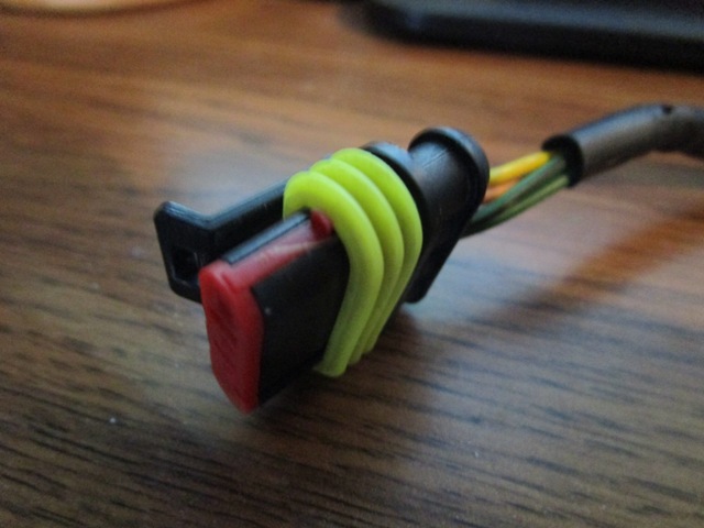 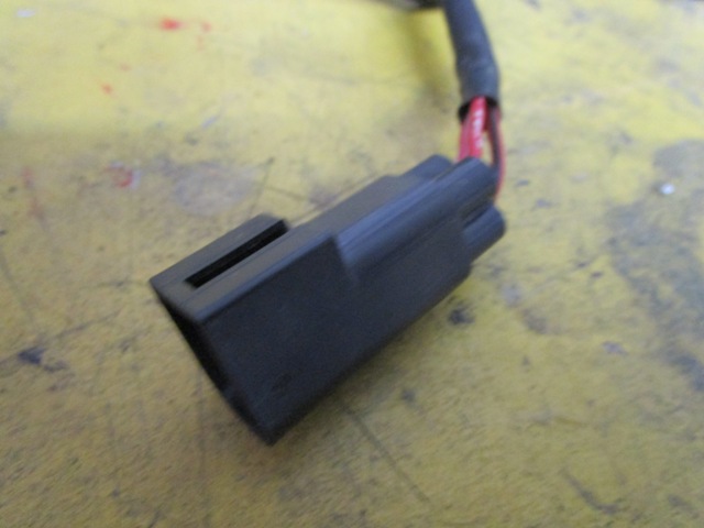 | ||
Jj5cool1 |
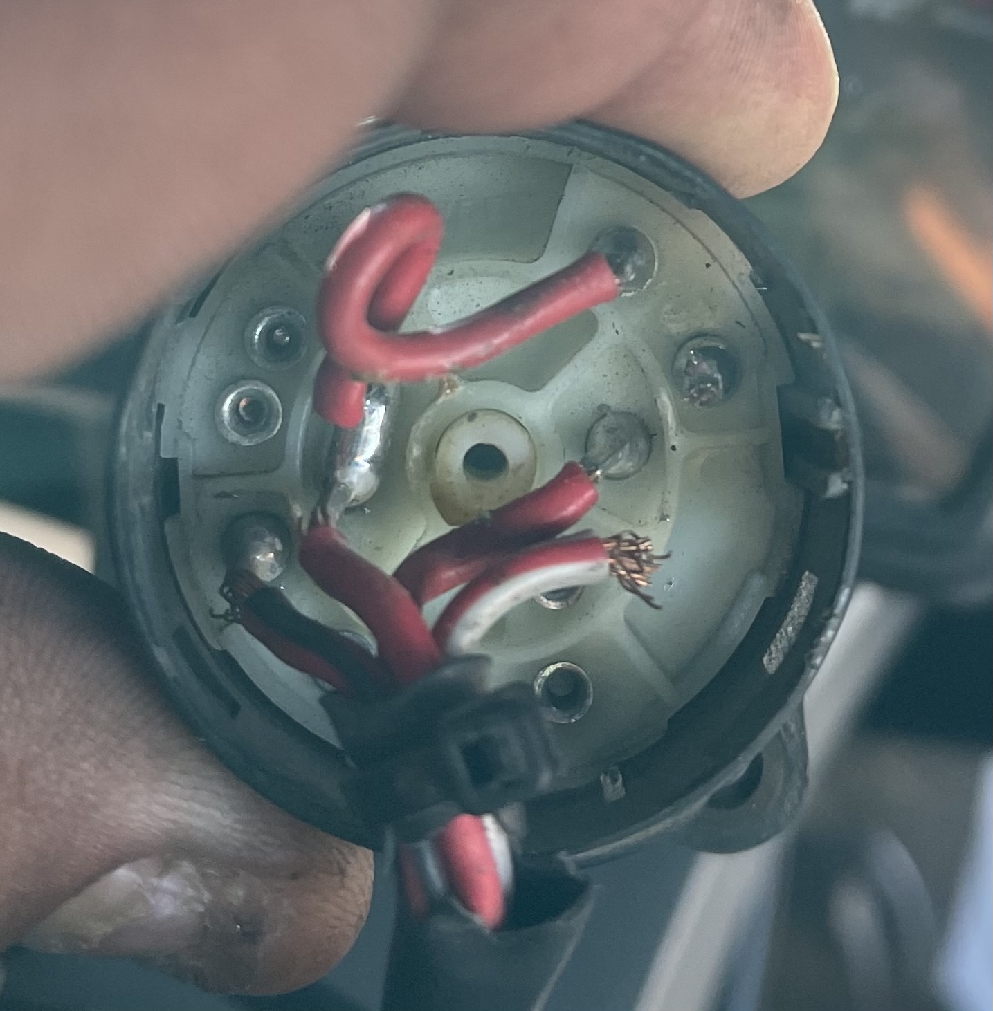
I just had the same issue. I ended up trying to re-solder the connections with longer wires (didnít go so well). What youíll want to do is either carefully pry off the ignition switch cover/cap from both and see which colors go where. Or if youíre familiar with 1125r electrical book, you can see what each wire is suppose to do at each key stop and test continuity with multimeter between the wires to determine which wires give you the correct result. Also Iíd be interested in the ignition switch (just the electrical part, not the key lock in case you ever wanted to transfer the lock cylinder to keep your original keys). | ||
Jj5cool1 |
 | ||
Skrip |
Thanks Jj5cool1. You get what I'm trying to do. However, I'm one step ahead of what you've suggested. After taking the cover off I was disappointed to find the configuration of the terminals aren't the same. So I hooked it up to the old multi-meter and found the right combinations to the ON and PARK positions. In PARK position GREEN to GREEN/BLACK are the only combinations that have continuity. In ON position GREEN to ORANGE have continuity and GREEN/BLACK to YELLOW have continuity. Makes Sense. But what I worry about which are the hot leads (coming from the fuse box) and which are switched hot. Not sure that I can but I don't want to burn up an ECU in the process. 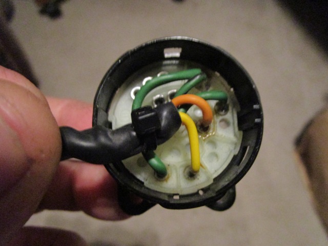 | ||
Skrip |
If I'm to believe EBR's wiring schematic (skeptical at best) then the hots would be YELLOW and GREEN based on their orientation in the connector. However I don't believe this is the case. I'm thinking the GREEN/BLACK and ORANGE are hot due to their orientation on the circuit board (for lack of a better term)compared to where the 1125's red leads are located. Maybe I'm overthinking this but I just want to be sure. Hopping someone on the EBR forum can give me a more definite answer.  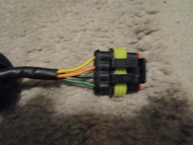 | ||
Jj5cool1 |
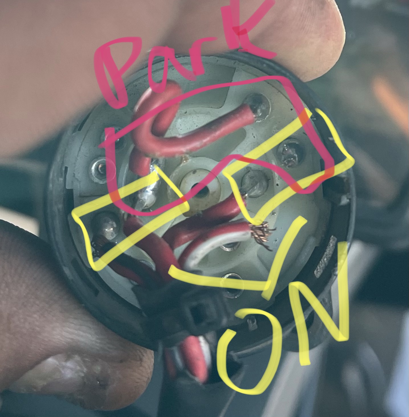
I tried my best (as you probably have as well) to find any info other than contacting EBR directly. The TL;DR: (As long as your multimeter readings are correct) 1 Green is PARK (Red/Grey) 2 Green/Black is supply (Red) 3 Orange is supply (Red) 4 Yellow is ON (Red/Black) There are no grounds involved, just completing circuits, so there should be no inherent risk if you wire them backwards or crossed (not responsible for any damage, proceed at your own risk). As you know (but to fill in anyone else who comes across this) the 1125R/CR is setup with the following wires: - Two Red wires supplying battery voltage at all times. - One Red/Black that completes the circuit associated with starting the bike (starter circuit, ECM, headlights, etc). - One Red/Grey wire that completes the circuit for the parking light (horn, accessory, parking lights, etc.) When the ignition cylinder is set to OFF or LOCK obviously no circuits are completed. But the two red wires should be Hot (supplying battery voltage) When set to PARK it completed the circuit for the Red/Grey wire and essentially you just get corner lights and canít start the bike. When set to ON/RUN it completes both the circuit for the Red/Grey and for Red/Black and you get headlights along with everything else and the ability to start the bike. The interesting thing is that it switches the supply voltage wire for the Parking Light circuit when going from ON to PARK. There is a jumper wire inside the switch from one hot wire to a pin next to the Red/Grey pin. I believe that wire causes the switch in supply voltage. | ||
Jj5cool1 |
 | ||
Jj5cool1 |
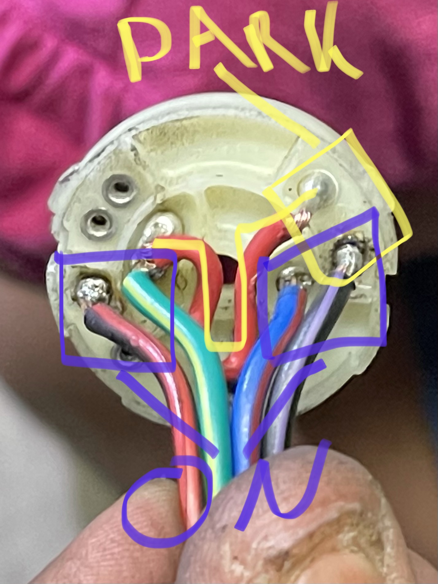 Clearer picture with new wires. | ||
Skrip |
I wired it up and it is running almost perfect. The weird thing is when switching from OFF to LOCK the lights blip on and off as if it's making a connection right before it goes to LOCK. Don't remember having this happen before. Oh well, no biggy. I also 3D printed a new cap with a slotted opening which allows the wires to flex a little more when they contact the headlight/instrument bracket. I also scalloped out the bracket to add additional clearance so I never have to repair another wire in the damn switch again! Hopefully. Thanks for your input on this Jj5cool1! 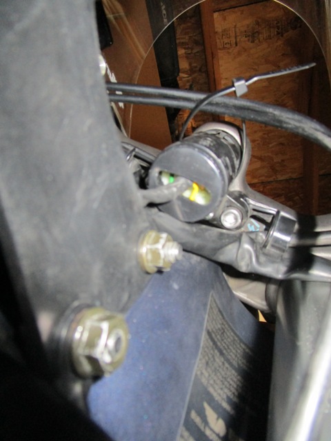 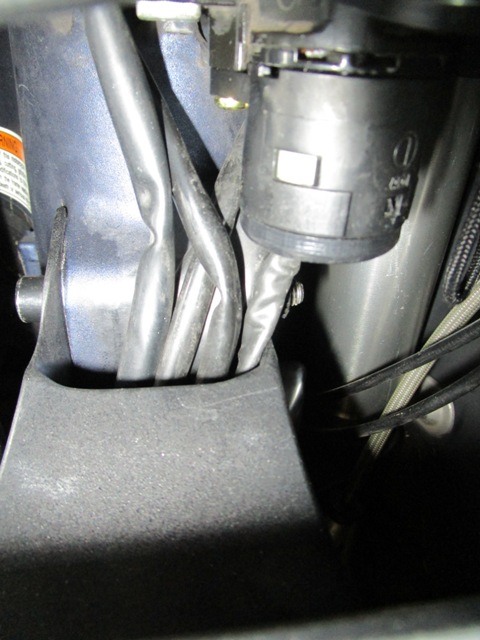 | ||
Mhpalin |
Great post I scalloped out my bracket 8 years ago and have never had a problem with the ignition yet  Zac came up with that mod I do believe. Zac came up with that mod I do believe. Thanks Zac | ||
Jj5cool1 |
Oh snaps, never considered slotting it. You could try switching the pairs to see if they stop flickering. Speaking of which, which wires did you connect with each other. Also, Skrip, any chance I can buy the broken ignition switch (just the electrical portion, no need for switch)? | ||
Skrip |
Yeah. Got the idea of scalloping the bracket from someone on this site, Mhpalin. Not trying to say I came up with the idea by any means. Props to Zac or whoever! Jj5cool1, the wires are exactly as you stated earlier. 1 Green is PARK (Red/Grey) 2 Green/Black is supply (Red) 3 Orange is supply (Red) 4 Yellow is ON (Red/Black) Sorry for not making that clearer earlier. And sorry. I tossed the old ignition already. |