| Author | Message | ||
Xbdave9s |
So my 2008 1125r started showing symptoms of a charging system problem about a week ago. Rode it to work and back on Friday with out any signs of a problem. Then yesterday I went out for a ride, after riding for about an hour, while riding slowly through a park the check engine light was coming on. A few minutes later in traffic the battery light was coming, lights were also coming on at idle. When the engine was above 3k rpm the lights would go out and come back on when at idle again. Got home and tested voltage, 11.3 at idle. The meter I have at home doesn't read A/C voltage. Tested resistance and all three legs showed approx 1.0 ohms. The connector from the Stator had been overheated and was slightly melted. So today I took the stator cover, had been wanting to check the rotor. Did not find anything overly obvious. Saw what appeared to be evidence that the rotor had lightly contacted the stator. I do not have the Socket here at home to remove the stator, will bring that home tomorrow and remove it. Also found the insulation in the wires near the connector going to the regulator had been over heated. So here are my questions to those of you who know these bikes better than I, 1) if the rotor was loose would I be able to feel the movement by hand? 2) Would you replace the stator, the regulator, or both? will try to post pictures later, need to shrink them | ||
Xbdave9s |
here are the pictures 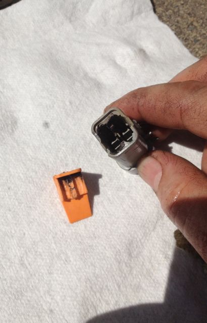 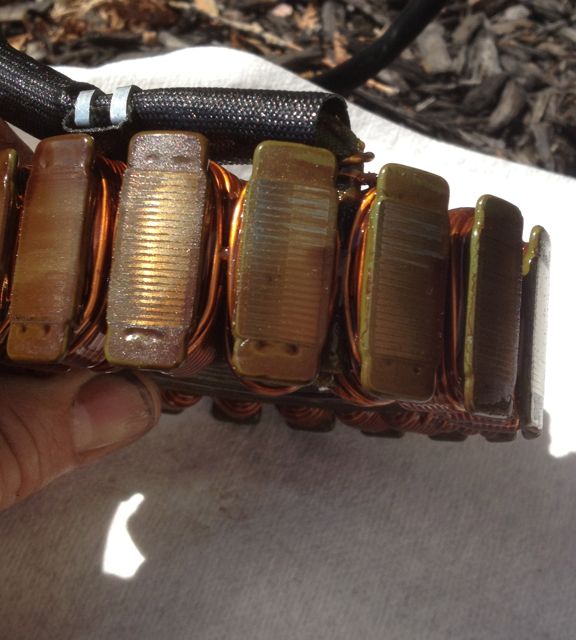 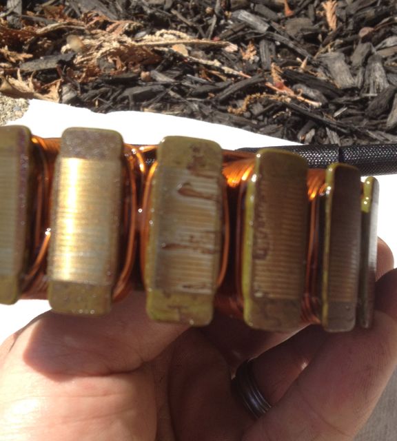 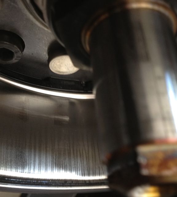 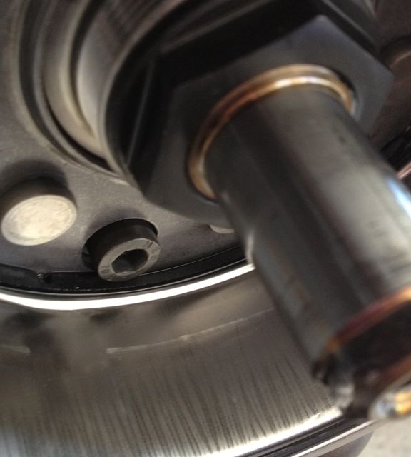 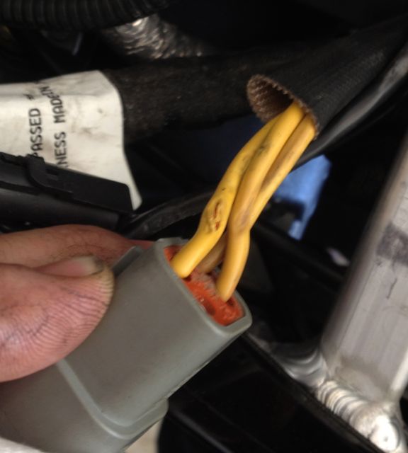 | ||
Timebandit |
Interesting that this is a 2008 stator/rotor. I can offer a few suggestions: 1. Don't do anything until you fix the plug/wires and take new measurements. If you are having plug failure/melting, then that problem is caused by resistance to current flow in the connection. That could be caused by dirt, oxidation, or mechanical trauma. Replace the connectors and fix the wires and then re-take your diagnostic measurements. 2. Don't put much faith in a typical handheld VOM to measure stator resistance, no matter who makes it. The impedance numbers you are trying to measure are beyond the accurate measuring range of common inexpensive meters. I don't know the spec for the resistance measurement for the 2008 stator, but 1 ohm sounds pretty high. I'm thinking your meter might not be very accurate in the sub-ohm end of the measurement range. The 2009 manual specifies that the stator is supposed to measure from 0.1 to 0.3 ohms. The problem is that you will NEVER get an accurate measurement in the sub-ohm range with a garden variety inexpensive/battery powered meter. Ohms law tells us that to accurately measure sub-ohm impedances you need high current, and even the better battery powered devices are notoriously inaccurate because they are limited in their current output. To accurately measure milliohms you need a meter that's specifically designed for that purpose with several digits of precision. Those are typically AC powered units. To get really accurate sub-ohm measurements you need a 4-wire kelvin meter. I've tested several stators using a Fluke 4-wire kelvin benchtop meter and the typical resistance value is about 145 mOhm and the typical inductance value is about 880 uH. Those numbers are highly repeatable without any significant deviation. On a toasted stator, I've seen the individual coils can measure anywhere from 60 to 200 mOhm and 50 to 700 uH. The range of what constitutes good vs. bad falls below the accurate lower measurement limit of many handheld meters. In other words, it would be pretty hard for a standard handheld/battery powered ohmmeter to produce a result that will reliably diagnose the problem. Unless you have a special purpose meter, you're going to have to rely on other tests. 3. To verify the stator's output you really need to perform the AC voltage test for each phase. There is a very good flow chart in the electrical systems manual for diagnosing charging system problems. To get to the right answer, you really need to perform all the tests. Personally, I wouldn't start hanging expensive parts on the bike until I've identified exactly what's wrong. If you don't have the proper test gear, your Buell shop should be able to do this at a reasonable charge. Good luck. | ||
Zac4mac |
I see a few mechanical issues in your pix Xbdave9s, but the stator poles look shiny and new. that's a good thing. Your wires near the plug are damaged, heat shrink or re-wire them. Problem at the plug was junk, insulating the pins. That increased resistance which IS heat and melted stuff... Odd the rubbing marks on the rotor/stator. Has any dealer ever worked on this bike for the stator/rotor? 08 and 09-10 are different size physically. 08 models have a pretty solid charging system. Wiring, not so much... Z | ||
Craigsmoney |
Time, I think the 1ohms resistance is when you are measuring the resistance between the stator and a good ground, making sure the stator doesn't have an open circuit. That is a correct reading. I had the same problem with my 09CR, with wires melted. I fixed the bad wires and haven't had a problem since. | ||
Timebandit |
No, Craigs, you've got that backwards -- you WANT the stator to have an open-circuit measurement in the resistance to ground test. If your stator to ground resistance is 1R then you have a shorted-to-ground stator. The stator-to-ground test measures the quality of the insulation in your wires, and should be in the MEGohms (millions of ohms) range. The problem is that most meters don't measure accurately at the high end of their measurement range. To accurately measure wire resistance, professionals will buy something like a Megger brand meter that is optimized to perform accurate measurements in the range of millions of ohms. The problem is that the average hand-held unit cannot accurately measure at such high impedances, and they falsely report a high/megohms Z as "open circuit" or "open loop". If you have a cheap meter, that's the answer you want -- just as is shown in the electrical diagnostics manual. | ||
Craigsmoney |
I just re-read my post. It is supposed to have an open circuit, and the voltage meter reads 1 with an open circuit. Thanks for the clarity on that. | ||
Timebandit |
I think I understand where the confusion is coming from. The pictures in the bootlegged manual that's been disseminated on the web aren't very clear. In the Buell 2009 Electrical Diagnostic manual, Fig 3-16 shows a handheld fluke meter who's readout says "OL". It's easy to mis-read the picture and interpret that alpha readout of "OL" as a numeric readout of "01" because the bottom part of the "L" isn't very wide. As good as that Fluke handheld meter is, it's still a handheld meter that can't accurately measure in the megohm range, so instead of providing an accurate megohm reading on the display it defaults to a reading of OL for "open loop" when it sees a really high impedance. Be careful with the readings you get from handheld meters, as they cam be ambiguous. OL would mean PASS while 01 would mean FAIL. If your meter is ambiguous about whether it's saying 01 or OL, the other tests should help you. The voltage output test should be abnormal/low volts in at least one lead if you had a readout of 01 (which would indicate a lead that is shunted to ground), while it could be normal (if you had a coil to coil short and no short to ground) with a readout of OL. (Message edited by timebandit on May 21, 2012) | ||
Xbdave9s |
Timebandit thank you for your knowledge and input, I know I should have waited till I brought home one of my handheld meters from work and tested the A/C voltage, but I also had been wanting to check/torque the rotor as I have been hearing a noise in this engine that I did not like for a long time. I was thinking of having a local armature shop bench test the stator for me. Zac4mac the dealer has not been in there as far as I know, the only repair the dealer ever did was to rotate the engine and install the heat shield on the frame for the vent dripping fuel. (not that did any good, still drips fuel!!!) One thing I did notice when I took it apart was that the locking tab on the connector for the stator was broken. Oh and thank you for your knowledge and input as well. | ||
Xbdave9s |
Does anyone know the part numbers for the connectors shells where the stator plugs into the regulator wires. As you can see mine is melted. I tried to search but was not able to find it. | ||
Baf |
A little late in response, but I just bought the connector for my new regulator. http://www.deutschconnector.com/products/deutsch_d tp_4-way_connectors.html You'll want either DTP04-4P and/or DTP06-4S, depending on which side of the plug you want. Get the stamped pins rather than the solid ones - it's what was on there OEM, and they'll be much easier to crimp. | ||
Footstuck |
Mate I would not and did not use that connector again after its failure. This is a documented and fairly common failure, given the small production numbers. I used one from a Honda (VFR i think) that had the double width spade connectors. You only need a Three Way block connector. I had a problem with my newly fitted Mosfet r/r, which I fitted it back in the original location. In Germany on the autobahn 3 weeks back the display went out completely all but some straight line led's in the the places that should have been displaying information. After about a minute it all came back. The symptom repeated itself and became more frequent to the point that it was occurring every ten minutes. I was getting the engine management light, battery light and voltage was showing 15.9volts. At first ,my response was to slow to 60mph and that allowed the battery voltage to drop. It turned out to be heat build up in the regulator. I mounted the regulator in its original slot, thinking that the improvement in its operation would overcome the poor position. . .wrong. While riding i had the thought to move the position of my left leg to improve the airflow to the vent hole. The voltage quickly dropped and no further issues. I monitored the voltage for the rest of the holiday, and if the voltage went beyond 14v (mine normally sits at 13.8v) i altered my leg position and the volts dropped quickly. I will think on how to increase air flow as i would like to maintain its position I'm now wondering if the overheat/mounting position of the reg/rectifier, may be a big part of all of the charge system issues(or all of it?)? I would think that the battery or another part of the electrical system would fail at that voltage continually (if un checked), that's presuming the original regulator reacts the same way or maybe it reacts in a more harmful way and when cool remains functioning correctly |