| Author | Message | ||
Robvanelst |
My theory is that other feeble electric components (ignition switch and wire-loom relay for example) cause peaks that blow the sensor. I can't tell anymore cos I am using a "speedo-failsafe" (a neat regulator, look at www.ukbeg.com, look for "Maz"  , but since I replaced ignition switch and that relay (regular bike/car parts, non-HD) it has fixed the problems I had with the indicator-relay and mysterious events where the rear-light would go on with ignition switched off. , but since I replaced ignition switch and that relay (regular bike/car parts, non-HD) it has fixed the problems I had with the indicator-relay and mysterious events where the rear-light would go on with ignition switched off. | ||
Blue02m2 |
My speedo on my 02 Cyclone works about half the time. Started at 3K miles. I have seen posts quoting the decision tree in the service manual that indicate that I should try cleaning the sensor. I have not bought the manual yet because my bike is still under warrantee. If cleaning the sensor is easier that dropping off the bike at the dealership, I'd like to try it first. Could someone fill me in on how to do this? Thanks in advance  | ||
Reepicheep |
Remove allen head bolt, remove sensor, wipe off metallic shavings with paper towel (sensor is a strong magnet) and replace. Pretty darn easy. If it is an intermittent failure, cleaning might fix it. Generally, the ones that die only stay intermittent for a short period of time before dying completely. | ||
Reepicheep |
Here is the latest filter I am building. We are still collecting data. No promises this will solve every problem, but it absolutely helps to some huge degree. When installing, don't cable tie down super tight, and make sure things have enough slack to vibrate. Some failures have been wiring related. Here are the parts I used on my last build. Total cost somewhere between $2 and $5, depending on what parts you have laying around. 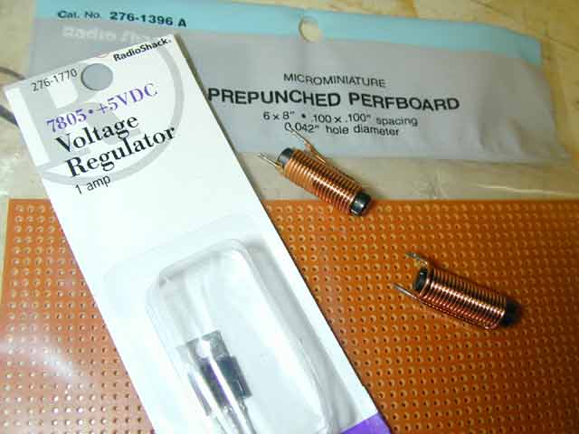 The sizes of nearly every part are not very critical. Choose a coil that is as big as you can find but still fits your packaging form factor. An old blown PC power supply has several inside, thats where these came from, but Radio Shack sells them as well. 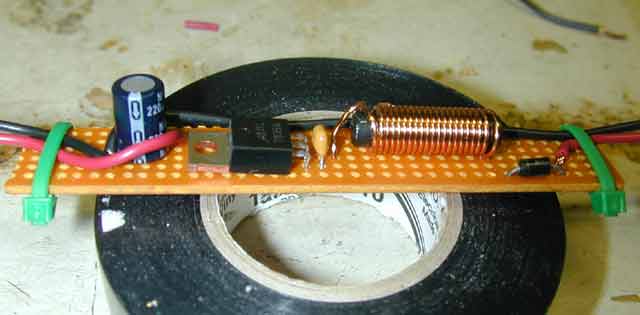 Front view of one of many possible component layout approaches. 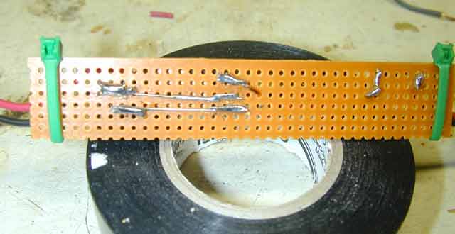 Here is a back view of one of many possible layouts. 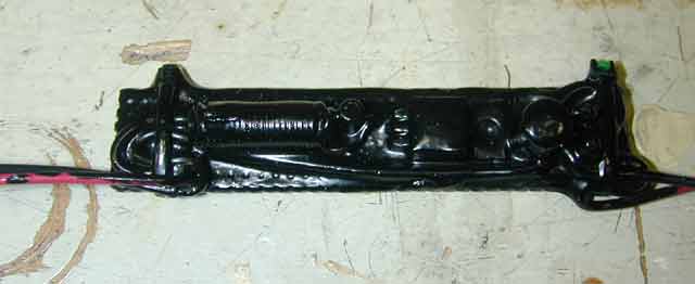 The whole mess properly strain relieved and potted with liquid electrical tape (a big thanks to whoever suggested that stuff, it rocks for all sorts of applications). Finally, the schematic. The left side comes from the motorcycle wiring harness, the right side goes towards the sensor. The top wire is the red wire on the harness, the bottom wire would be the black. You will cut these red and black wires on the sensor side of the connector, and insert this filter in series. The LED and resistor are optional, they indicate if the regulator is working, and might help it regulate better by drawing a little more current. I don't think the values of C1 and C2 are particularly important, but make sure whatever capacitors you use are rated for the appropriate voltage, particularly on the input side (which could easily reach 14 volts or more). The voltage rating on the caps is the maximum they can stand before blowing up, so make sure the voltage is as high or higher then what I have listed. 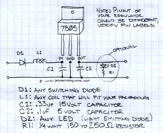 Sometime soon, when I get a little time, I will do a better write up and post more detailed build directions here, with a nice summary of all the information about the failures we have accumulated. They are an easy build, but if don't want to tackle it email me offline and I will build one up and ship it out to you in less then a week. (Message edited by reepicheep on May 27, 2003, %time) (Message edited by reepicheep on May 27, 2003, %time) | ||
Reepicheep |
Oh yeah. The stripe on the diode is the negative side. Think of it as the line on the diode schematic symbol, the arrow points to the line and designates the direction current will be allowed to flow. | ||
Hootowl |
Reep, Holes or electrons? | ||
Reepicheep |
smartass!  Do you know what the part in there actually does hoot? I was assuming it was some sort of magnetic field sensor (hall effect? Never played with one), probably with a built in comparator of some sort. But back in the voltage regulator discussion somebody (gotta go back and look) suggested that it was a full CPU with wave shaping. Seems un-necessary to me and that it is probably a CMOS FET type "analog" chip with just a few components, but that is pure speculation on my part. Anybody know? Not that it would make much difference I suppose. If we loose more then a couple sensors with the new setup (that we all kinda collaborated on) then we will move to an op amp setup and filter every input and output. I hope we don't have to go that far though, parts would be cheap but the build would probably exceed the typical tinkerer. | ||
Bluzm2 |
Bill, I think the guts of the sensor are a hall switch with a wave shaper for input to the speedo. A full CPU would be gross overkill. | ||
Hootowl |
I know it's a Hall Effect sensor, but that's about it. There's got to be something else going on in there though, or we wouldn't be seeing so many failures. | ||
Mikej |
Could the magnet be reversing polarity????? | ||
Reepicheep |
I don't think so Mike, I took mine apart down to the semiconductor (no small task) and it was toast. You can ping the dead ones with an ohm meter and see an obvious difference between the living and the dead even without the sensor powered up (which the magnet would not effect). | ||
99x1 |
"I think the guts of the sensor are a hall switch with a wave shaper for input to the speedo. A full CPU would be gross overkill." The gear tooth sensor is kinda complicated - magnetic strength changes with temperature, the wave shape is not a nice digital shape, air gap is critical, and heavy vibration is present - so it has to compensate for any change in the flux field of the magnet (except for the true effect of a gear tooth near the magnet). Most self calibrate and some do use processors - see Allegro sensor. I have no idea what is in the Buell... | ||
Bluzm2 |
Hmmm, Maybe that's why they are so friggin expensive! | ||
Anonymous |
Don't forget about mechanical failures. The filter will help with all the electrical failures but it can't prevent trans oil from getting in one that's badly potted. A while back someone was asking about XB failures, the XB9S sensor is powered by 5V, the XB9R is 12V for now | ||
Hootowl |
My 99X1 sensor is powered by 5 volts  I find it strange that the S and the R are different. I wouldn't have thought that. | ||
Reepicheep |
Thanks Anony. Hoot... Which was released first  | ||
Anonymous |
<quote> for now Key words? | ||
Steve_a |
This was cut from a longer article in the August CW for space reasons, but I thought it might be appropriate to share it here: ... In addition, Buell and Stefanelli [Buell engineering lead on machines powered by XB-class engines] mention how actively the company is pursuing any problems reported. A warranty review team, comprising Stefanelli and other functional group leaders in the company, meets once a week to review what's happening out in the field. Each warranty item is investigated until the cause is understood “Every single issue gets looked at,” says Stefanelli. “Last year, we made specific actionable changes to the vehicle, our processes, and our supplier's processes to address the top 20 warranty items. Of those top 20 warranty items, a substantial number of them were of packaging of the motorcycle in the crate; so we changed the packaging. Some were simple little durability type things, like the speed sensor for the speedometer. It turned out to be three problems. One was a bad batch of speed sensors, some wires had been cut because they'd been over tightened. All that had been resolved when the 984 was launched. But our new sensor wasn't good enough, and we still had a few failures. We got a new improved sensor from the supplier. It still wasn't good enough. On a handful of bikes we were getting voltage spikes that were killing the sensor, so we added a 5-volt regulator to the circuit at the time of the XB9S introduction. There’ve been zero warranties on speed sensors on Lightings with voltage regulation.” It’s this type of work that Stefanelli hopes to “move us down to zero warranty claims.” . . . | ||
Blake |
Thanks Steve. I missed that, err, no, I just haven't received the August issue yet. Should be here in a few days though. Any news on the front wheels?  | ||
Steve_a |
Blake, ummm, maybe that was intended for the September issue; in any case for the one that just shipped to the printer today. Not working out of the CW offices, it's hard for me to keep track of what month will be on the cover; all I know is that I'm working on something for the current issue. And I did ask about the wheels when I was out in East Troy. They did tighten run-out and flatness requirements on the wheels and the front brake disc after production started -- a tolerance stack-up issue, I think. But Erik and Stefanelli claimed they haven't seen any significant problems with wheels show up in their warranty claims, nor their extended durability tests -- which run in part over some very bad surfaces. | ||
Blake |
That's good news. | ||
Reepicheep |
Fantastic Steve, thanks so much for getting us straight info in a timely manner, and bringing it to our attention here. I just bought a pile of the 5V regulators to help folks out (50 cents each in bulk) and will be fabricating some PC boards so I can whip the things up in no time flat. | ||
Court |
Bill: When you get those whipped up, let's see if we can implement a procedure to get them in the hands of Buell owners who need them until the factory can sort their procedure out. We can also figure out a way to get you paid for your parts. Badweb has a reputation of responding quickly and unemotionally as well as for being quick to the fix. I suggest we call the program "Badwill"  Steve A: This is very cool, having your knowledge getting in the hands of the end user FAST. This continues to become a board with a wider and better range of resources from a host of disciplines. THANK YOU. Court | ||
Bluzm2 |
Bill, I'm a lazy fart. I've not built mine yet. I'll take one off your hands. Are these splice in type or plug and play. Thanks! Brad | ||
Reepicheep |
If you send me the new sensor, I will solder it in for you and it is plug and play. Otherwise, you just need to wire it in. I prefer solder, but I bet the right sized wire nut would do just fine as well, especially if you slather it with liquid electrical tape after the fact. I would make it fully plug and play, but I can't get the Deutsch connectors easily (nor do I have the crimp tool for it). Send me an email with a mailing address. Bill | ||
Ryan_m2 |
The only source I've been able to find for the 3 pin Deutsch connectors are H-D dealers. Between the repair manual and the parts book for my '00 M2 I was able to find most of the part numbers, and the parts counter guy was able to help me with the remaining pieces. Three parts will be needed for any connector - the housing, the lock wedge, and the pins or sockets. I have the part numbers for most of those but I could send them to anybody who wants them. I'm still using the earlier design filter from Reepicheep (just a choke and a diode) with the current design speed sensor, but I may consider going to this new design with the 5V regulator. Ryan | ||
Reepicheep |
 Just got back from Mendelsons Electronic Surplus in downtown Dayton, getting parts for speedo sensor filters. Just got back from Mendelsons Electronic Surplus in downtown Dayton, getting parts for speedo sensor filters. This place has (literally) about 4 acres of electronics and electrical surplus to pick through. Everything from electrolytic capacitors the size of paint cans to parts from old Wright Patt AFB flight simulators. Rumor has it that there is a complete Huey in zip lock bags hidden on the second floor (public only allowed on first and third). My head hurts, my vision is blurred, and my ears are ringing, but I got the parts I wanted at a laughable price. Talk about engineer sensory overload. Ever browse about 30 feet of shelves 6 feet tall filled with just inductors? Oooowwwww! Anyway, the parts are here. I will lay out the PC Board and try and try and fabricate a few by this weekend. | ||
5liter |
Just had my speedo sensor replaced under warranty. 2002 S3T with 4600 miles when it quit. | ||
Reepicheep |
Got the parts, designed the board...  It is around 2"x.5" | ||
Reepicheep |
Reworked the board a little. Geesh, this thing is going to be *TINY*. It will be very cool. I will be tied up this weekend, but hopefully I can get some fabricated early next week and get them shipped quickly. Once I get the boards made, I should be able to throw filters together in no time flat. All the parts are acquired and waiting. So thanks for your patience everyone, I should get them out to the people waiting soon. |