| Author | Message | ||
M1combat |
I have a dream... I'd like to keep my displacement at 1203, but get to about 120HP at the rear wheel. I don't want to use a turbo because I'll lose my exhaust and I don't want to deal with lag. My thoughts currently are to use a custom machined pulley on the crank that can also drive a belt. The belt would run upwards out of the primary and to the super charger. The charger would reside to the left of the cylinders (it "looks" like there are some useful mounting locations there, and it would be fairly out of the way). The ?charged intake tube? would run a little forwards and then up through the frame and to the intake. Maybe through an inter-cooler in the airbox. Any thoughts? Can anyone think of an issue doing it this way? The first ones that come to mind are of course contamination of primary oil due to the fact that it's no longer a sealed area, and oil on the pulley (that would of course make its way to the other pulley on the charger). My favorite solution to this so far is to go with a dry clutch... Any thoughts from you guys that run turbo? Maybe the extra portion of the front sprocket/pulley could protrude from the primary cover and then I could get a sealed bearing? This of course would require machining the primary cover for the bearing. I entertained the thought (briefly) of maybe running another sprocket off of the primary chain in between the front sprocket and the clutch basket... Anyway, any help would be appreciated  . . | ||
Mikej |
Someone just in the last week was looking into this, not sure what thread it's in. In the mean time here's a link to go browse: http://www.cas4.com/Supercharger-Turbo/Supercharger/EM/Supercharger-EM.htm  | ||
M1combat |
That's pretty close to exactly what I was thinking... but the Rotrex is about 1/2 that size or a little less and doesn't have a carb on the front of it  . It's also oil cooled and contains it's own oil reservoir and oil pump. I'd add an oil cooler to the right side of the bike. . It's also oil cooled and contains it's own oil reservoir and oil pump. I'd add an oil cooler to the right side of the bike. | ||
Benm2 |
There's a company that makes an electric supercharger, I think its something simple like "electricsupercharger.com". It's actually patented. It only works at full throttle, when the throttle position sensor tells the boost fan to come on. Probably not the power gain you're looking for, but neat anyway. I'd probably try to re-use the stock left side cover, and modify the primary sprocket to work as a "PTO". My suggestion, for what its worth: 1. Don't mess with the primary area too much. Keep the stock oil & wet clutch setup. 2. Modify the primary sprocket to accept a machined output shaft long enough to drive the supercharger pulley. Tolerances are going to be really important here. 3. Modify the primary cover to accept a lip seal that matches the shaft you sized. Preheat the cover, then fill-weld as required to get some machining meat. Since it should only be a seal holder, just add enough meat to bolt on a seal cover. That should give an output shaft that you could use on the left side of the engine. Machining of all of these parts will be critical for it to work, of course. You could allow yourself some room by making the seal cover move a little by using "generous" bolt holes to attach it to the primary cover. That might allow you to move the seal once its on the bike to line up with the shaft. Neat project! Another idea would be to use a fan supercharger driven off a high-powered brushless DC motor. For short bursts it would suck down the battery, like a great big starter. For 20-30 seconds at a time though, it could be pretty cool. Such a system might be able to produce quite a bit more pressure that the electric supercharger that's being advertised on the site I listed. | ||
M1combat |
It needs to be belt/chain/gear driven off of the engine/primary/cam etc. I'm looking for power increase across the board at all times. If I didn't have that requirement I would use a turbo  . . On point number two... What if I were to make a NUT that holds on the primary sprocket and IS the output shaft for the blower pulley? I would imagine it would require a VERY deep socket for installation, but at this point, that's the least of my worries  . If it had a hex nut machined to the bottom of it (or even welded if I could be assured that it's square) I could retain the retainer (I assume it has one a lot like on the front pulley in the final drive?). . If it had a hex nut machined to the bottom of it (or even welded if I could be assured that it's square) I could retain the retainer (I assume it has one a lot like on the front pulley in the final drive?). That SOUNDS like a fairly simple thing to machine... But I'm not a machinist... It would be keyed just like the output shaft of the crank (unless there's a different setup commonly used for belt pulleys) and I could find a way to balance it. Point three sounds doable. Anyone know if the dimensions and thread properties of that side of the crank are in the service manual? I doubt it... Sounds like I'll need to open it at least once to measure it. ___________ To square the nut on the bottom of the blower output shaft... The output shaft would be threaded with the same threads as the nut. I'll run a bolt with the same threads as the output shaft through the nut and then into the blower output shaft. Tighten them together (not extremely tight so as to not have a very stressed weld once removed) and weld. Wouldn't that produce a true piece? I know a guy that's a very good welder and could probably produce a weld that's fairly balanced... | ||
M1combat |
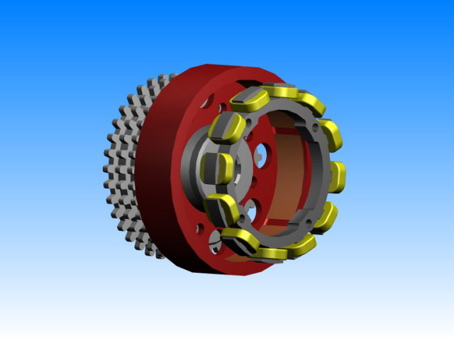
Something like this... a little... kind of anyway... well, I'm sure there will be a couple changes... fundamental ones most likely... but you get the idea...  The bottom end by the nut is threaded. The keyed area at the top wont go all the way down the shaft, and the keys will be even and correct for whatever pulley I choose. There will indeed be six points on the nut  . . It's nowhere NEAR to scale or even very close in relative dimensions I'm sure  . . I wish I had AutoCAD... | ||
Firemanjim |
Donald,there is an outfit in Berkeley CA that is working with the Rotrex superchargers making install kits for a bunch of bikes.They had Buell listed as one of the upcoming kits.Of course I cannot remember the site but did send off an e-mail to one of the guys as he posts a bunch on the Hayabusa site/turbo section.If he answers I'll let you know.They had some nice pics of a Gix 1000 with it on. Oops,found it,look here-- http://www.calisuperbikes.com/ | ||
M1combat |
Thanks Jim, it looks like they don't have the Buell listed anymore, but I'll try to change that  . . | ||
M1combat |
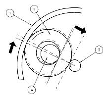
Apparently... The issue with the Rotrex unit and a packaging constraint that requires the unit be mounted to the left side of a bike is that this will run the super charger in reverse (unless of course, if we want to run the engine in reverse  , but this will create a number of other problems , but this will create a number of other problems  ). From what I've been told, it's possible to place a turbo vane in the charger in place of the one that comes with it and then the reverse thing isn't a problem in and of itself. It does create the issue that the traction drive no longer works... ). From what I've been told, it's possible to place a turbo vane in the charger in place of the one that comes with it and then the reverse thing isn't a problem in and of itself. It does create the issue that the traction drive no longer works... If you take a look at this diagram, it indicates that the line running center to center from the high-speed output shaft (#3) to the stay (#4) is not parallel to the line running from the high-speed output shaft (#3) to the annulus drive ring (#1). This indicates that there is an offset of a certain number of degrees. Obviously, this is what is responsible for the “traction” drive. Can you think of a way to rotate the housing that the stays (#4) are machined into in order to move them to where they are the same number of degrees off the line from the output shaft (#3) to the Annulus Drive ring (#1) but in the other direction? This would, as far as I can tell… allow the unit to run in reverse just fine. One could then use a turbo vane and be in business.  | ||
Natexlh1000 |
Wouldn't this project be a lot easier if the power was taken from the timing side? The intake is on the right; plumbing it would be more easy. | ||
Natexlh1000 |
OOPS! I didn't read the fine print. I thought this was for a tuber. | ||
M1combat |
No problem  , I suppose I should have made it clearer. Apparently a tube frame Buell can use a Rotrex Super charger fairly easily... , I suppose I should have made it clearer. Apparently a tube frame Buell can use a Rotrex Super charger fairly easily... | ||
Bud |
http://www.tts-performance.com/catalog/product_info.php?cPath=509&products_id=42 45 http://www.bike-pix.com/forum/viewtopic.php?p=48663#48663 options ? | ||
M1combat |
Yeah, I've seen that before, but it's not where I want it  ... ... It can be placed better, so it should be  . It looks like a viable option if I can't work this one out though. . It looks like a viable option if I can't work this one out though. | ||
Benm2 |
M1, I would be cautious about making a special nut to replace the stocker. I think the stock nut is pretty special hardware. I'd still vote for modifying the primary pulley to accept a "PTO" shaft. I'd machine a deeper larger-diameter cutout into the stock sprocket, and add a new bolt pattern. I'd go for a light interference fit between the new output "thingy" and the c'bore in the sprocket. I'd think you'd be more assured that such a part would stay concentric. I'm curious why you'd head down this path, though. For the power you want, it seems the 88" conversion might be alot easier than what you're undertaking. Plus, that conversion wouldn't make the bike heavier! But if you want to do it, then I'd check out either AutoCAD LT, or for 3d try Alibre design. I use Alibre for my 3d cad work, makes pretty pictures!  | ||
M1combat |
I figure at some point I'll end up with 88" and a super charger. Maybe not  . That would be pretty scary... . That would be pretty scary... I don't intend to replace the nut exactly. I was thinking that welding it to the bottom of a shaft that has the same threads as the nut while tightened together on a bolt with those threads would produce a straight part. Once placed on the out put shaft of the crank the part shouldn't be stressed much different than when it was welded. I don't think I have enough room for a PTO shaft as such... I think it needs to be a straight extension of the cranks output shaft. I looked around but didn't really find a pto shaft that looked like it could really be packaged between the crank sprocket nut and a bearing mounted in or just outside of the primary cover. Hmmm... any ideas for taking drive from the starter gear on the clutch basket? That would put the pulley (or gears) on the correct side anyway and I wouldn't have to do anything funky with the intake... Thank you for the reply. | ||
Greggearhead |
I have done some work with WBT, Inc. who manufacture a supercharger kit for the TwinCam 88 based fuelie engines. Not of much help here, except that you can see on the website several autocad drawings that show the drive setup from the crankshaft on the right side of the engine. www.wbtinc.com | ||
M1combat |
Thanks for the update. It beginning to look like this will be a reality fairly soon from Hillbilly-Motors motors as their issue was fueling the charger. With the direct link device I'm thinking that's now possible. | ||
Diablobrian |
Leave it to Jens to come up with the most over the top mods for the xb Buells! Go Jens! | ||
Jens |
M1, use the OEM steelsprocket dehardened it and superturn it a bit out that it accept centric a plate from the outside. Finsih the threads (holes from the alternatorrotor) from the outside. Harden the sprocket again. Now you superturn a plate with the driveshaft that you screw with countersinkscrews to the sprocket. Now you have only to get a hole in the primarycover and to get the oilseal done, but thats another story. Have fun! Jens | ||
Diablobrian |
You make it sound so easy Jens! I will help a little here since technical terms don't always translate well. By superturning I believe Jens is talking about turning the face of the sprocket to create a registering step on the face of the sprocket concentric to the shaft. Making the hole in the cover should be easy, building the case up so you can put in a shaft seal can be tricky. Cast magnesium can be tough to weld. | ||
Jens |
You got me Brian! At the seal the problem is that you never hit the center of the driveshaft with the hole in the cover. So you need to make a ""shield" that carry the seal and what you can move a bit. It will center itself when you turn the crankshaft before full tighten. Jens | ||
Diablobrian |
Been there done that! One of my former professions was as a prototype machinist (old school, manual). Among the jobs were some jobs for ships in the San Diego ship yards of various national registies. So I've dealt with similar translation jobs and I was not in any way trying to have fun at your expense! I do not want to come off wrong on it because of a mis-understanding due to the lack of inflection that comes with internet discussions  | ||
Jens |
Its not so easy in a foreign language when it goes into technical details... (-: | ||
Panic |
power increase across the board at all times The Rotrex won't do that, nor will any other centrifugal type since boost ~ RPM^2. For boost throughout the range you need a positive displacement (twin rotor or eccentric vane). More info: http://victorylibrary.com/supercharger/super.htm | ||
Blake |
test |