| Author | Message | ||
Chasten |
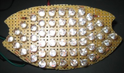
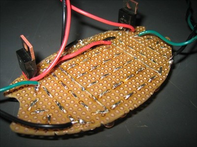
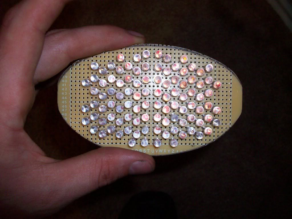
so, a little while back i completed this project and just got around to posting the info. i was frustrated with aftermarket companies selling the integrated taillight circuit board for so much money. it couldn't be that hard or expensive to build one in the garage, right? well... actually, no. i'm sure i'm not the first to complete this project, but i did it totally from scratch... i had not built any circuits before, so keep that in mind before submitting your technical critiques. also, this was intended to be (and in fact is) the first working prototype, not the final build. however, it ended up working so well, that i am still running the prototype. total cost of the project was a little less than $50 in parts, and a good deal of time in development before building the board. anyway... here are a couple of photos:   and here are a couple of (not-very-good) videos of the thing operating: http://www.vimeo.com/1033610 | ||
Iamarchangel |
Curious to see how the turn signal shows up with the brake light on. | ||
Voofighters |
wow.. i like that..i like that a lot! i clicked the link to the video..very nice. i was thinking of doing something similar but couldnt work out which LED's to go with.. Which ones did you decide on and how did you implement the brake light vs. running light? | ||
Mr2shim |
Awesome work man! I thought about doing this... I don't have the patience now days though. | ||
Simple |
very nice! on a scale of 1-10, 10 being most difficult, how would you rate the build for a mechanically inclined person? this looks like something i wouldnt mind tackling, as i was planning on purchasing the same deal from a vendor in the next couple days for a bit more $$! could you do a writeup please!  and how about a list of parts/part numbers and or a place to purchase the individual parts! (Message edited by simple on July 20, 2008) | ||
Kakkarott3 |
Excellent work! [redacted] Did you have to change the flasher to avoid fast blinking? (Message edited by Blake on July 22, 2008) | ||
Teddagreek |
PM the guy for you interests... This is a good thread I'd hate to see it yanked.. Good work... If you don't mind would you post your schematic.. I like how you got the leds to dim then go bright, that is the right way.. Are the Mosfets for the signals... This is on my list if I ever got some extra time.. Have you thought about using a Lumileds? | ||
07xb12scg |
Nice job. I'd think about doing this, but I don't trust people to see the turn signals when they're integrated into the brake light. It's just one of my "things". | ||
Chasten |
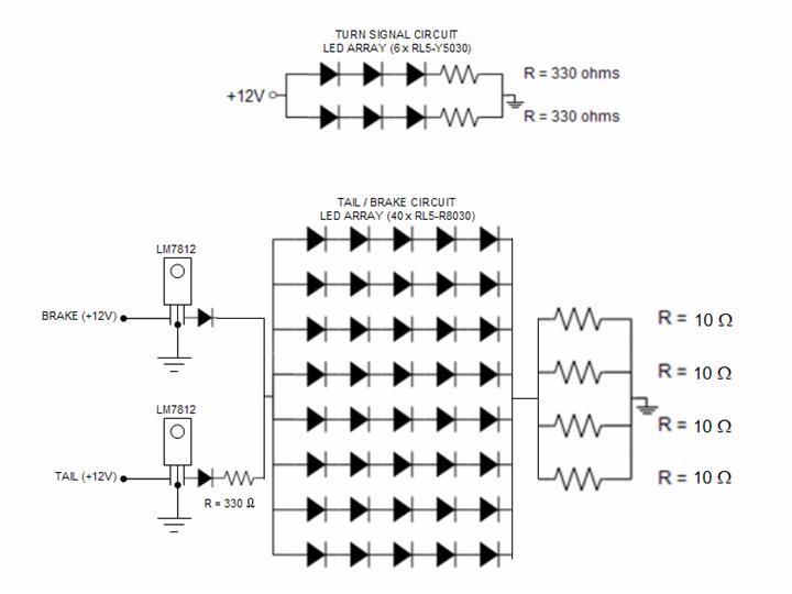
thanks for the compliments, guys... re: brake light on, turn signals on... um, i haven't really seen that. i could do another test video, i guess... here's the thing: i don't really ever see the back of my bike while i'm riding it. i ran the idea by my wife of her driving the car behind me and recording video so i could see the "real-world" performance of the lights, but she kind of thought i was joking. re: build details and parts the LEDs are from "superbrightleds.com". i wouldn't necessarily recommend that supplier, but i also wouldn't NOT recommend them. sourcing the LEDs was a fairly quick process as this was intended to be a prototype. if i built it again, i'd probably take more time for LED research. i like the LUMILED products a lot... anyway, i'll try to put together a complete parts list in a future post. for build difficulty, on a scale of 1-10, i would put this at ~3 depending on your experience with a soldering iron (i had basically none). none of it was really DIFFICULT, as much as time/patience intensive. the one crucial thing is the actual circuit design. there are many ways to accomplish the same thing, and the way i chose is probably not the best, but i was trying to keep the design simple and the number of components low. i might try to post a drawing of the circuit, later, but here is the written instruction: * tail light is all 40 red LEDs, operating at ~10% normal current (current limited by resistor). * brake light illuminates all 40 red LEDs at nearly 100% operating current. power to LED array bypasses the limiting resistor for the tail light. * each turn signal is an isolated circuit. * therefore, there are four power inputs and three grounds, just like the factory setup. i DID change the flasher to an electronic unit due to "hyperflash" symptoms. this condition was not much of an issue while still using the OE front signals, but became a bigger deal when all the signals were LEDs. re: more for sale umm... i'd definitely consider building another unit for sale. it could be a lot of fun. to get my time out of it, i'd probably have to sell it for ~$150. sooo... not that much of a savings compared to other products that are available. the whole reason i made my own was not just to save the money on the purchase, but because i thought i COULD. it's kind of cool knowing that i made that part from bare components... | ||
Chasten |
a general comment on the visibility of turn signals in integrated tail lights... visibility is somewhat decreased. however... the people who see turn signals still have no problem seeing these. the people who don't see these turn signals are the same people who don't see the OE signals, or your motorcycle at all. | ||
Not_purple_s2 |
Awesome, I'm thinking of doing something like that but I'm a little hesitant about integrated turn signals, I'd probably just do an led tail/brake setup. I'll have to dig out my EE Systems book... I hated that class. But you've definitely sparked a new project for me. Ex-nay on the ale-say. The powers that be here have a very short fuse when they suspect someone of soliciting without being a sponsor. You're obviously not doing that but I just thought I'd mention it before it became an issue. However, homemade build projects with lots of info and pictures are always welcome! Great work! Can you upload any video of it functioning? | ||
Rah7777777 |
Nice write up. although, something like this is exactly how XB Lights got started :-) Posted a "how-to" then someone suggested selling them, after much thought I got sponsorship (which isnt cheap) and started looking for buyers. then realized the circuitry would need a complete make-over to ensure it would be safe and last the test of time. Next thing you know i'm spending hours on hours (and hours!!) going through all the possible ways to run the circuitry looking for the best option to keep constant current at all LEDs and make sure there are various protection circuits in place for transient voltages, spikes and what not. I ended up having to use 2 boards, one all LED's and second for the regulation circuitry (voltage regulators, heatsinks, and numerous diodes, resistors, capacitors, etc...) Then the web site building.........WOW! Talk about time consuming and I didnt even do the HTML writing, the little lady did. (which might I add just received a complete make over) I would have never imagined it would have been as time consuming as it has turned out to be. But I enjoy it. For the time I would have to say the profits are pretty low. But not horrible. In the pic, I can't tell if those or voltage regulators or not, if they are I would highly suggest placing heatsinks on them for added protection. But i'm not too sure how much current is going through them with the LEDs used, so it might be okay as is. Keep it safe!!! -Robert Hall xblgihts@yahoo.com www.xblights.com | ||
Chasten |
hey rah... the stuff you have at xblights is basically exactly what i set out to create for myself. i would have just purchased one of your assemblies, but i wanted to try to make my own. i could see how running that business could become a nice side-project that consumes ALL of your time. your suggestion about the heat sinks on the voltage regulators is precisely the kind of thing that i expect you would learn after all of those hours on hours of development and testing. i don't think i NEED them, but i will keep that in mind if i encounter any issues. the example in the photo was seriously just a first attempt and is in no way a refined product. i'm sure that will be even more evident when i post the circuit schematic. do you mind if i ask you how you cut the PC boards you use? are you having them stamped out? (i ask because yours look VERY precise... i buzzed mine out by hand with a die grinder.) oh, and just to clear things up... for the record, i am not soliciting sales. | ||
Xl_cheese |
I took a stab a while back as well.  My board replace the entire reflector in the taillight. It was time consuming to say the least. I also think I did not use the ideal LED. They are very directional and I had to play with them a bit so that the brake light was it's brightest from directly behind the bike. The Red lense refracted the light which made it tricky. I'm planning to do another one with LED that advertise a much wider viewing angle. that should make it better. You'll notice that cars with LED taillight do not have a shaped lense. At night I'm able to light up the cab of the vehicle behind me.  | ||
Xl_cheese |
I'm not sure the brake light circuit is correct. How do you know what the current is? You need a limiting resistor on the brake light as well. From what I understand if you want each LED to double as the running light and the brake light then you need a timer circuit. IE 555 timer. Operate the running light at some frequency that is faster than the eye can realize it's flashing. The brakelight would be a much higher frequency. I think that is how cars do it. The light I did I just went the easy way and used 40 LED's for the running light and the other 60 would come on for the brake light. All operating at the rated current of 20mA. Get your LED's off of ebay. They are MUCH cheaper. I originally purchased the 33,000 MCD version. It's rumored that if you stare directly at my brake light your vision will be altered... | ||
Simple |
where do you guys get the actual board from? | ||
Xl_cheese |
Get the board from Radio shack. I paid $30 for everything. Board - Radioshack LEDs - Ebay 100x Resistors - Frys. 100ohm 1/8W | ||
Chasten |
parts for my build, other than the LEDs came from Radio Shack (including the board). again, not a recommended source, but handy in my case when i would just go and browse for something that would do what i wanted it to do. | ||
Simple |
cool, i will have to find out where the closest R/S is to me. looks like this is going to be my next little project along with a tail chop. thanks fellas and good stuff!! | ||
Chasten |
so here is the schematic of the circuit i made. you should be able to see how the dual-mode works on the tail / brake.  | ||
Teddagreek |
Thanks... Very Nice.. | ||
Rah7777777 |
http://www.badweatherbikers.com/buell/messages/171 43/379540.html?1216952261 not letting any secrets out, but the boards form R/S will warp in the heat after a while. My very first one was built with a board from there and after a year it came loose from warpage....... | ||
Skully |
i was frustrated with aftermarket companies selling the integrated taillight circuit board for so much money. it couldn't be that hard or expensive to build one in the garage, right? well... actually, no. Posted a "how-to" then someone suggested selling them, after much thought I got sponsorship (which isnt cheap) and started looking for buyers. then realized the circuitry would need a complete make-over to ensure it would be safe and last the test of time. Next thing you know i'm spending hours on hours (and hours!!)... Then the web site building.........WOW! Talk about time consuming and I didnt even do the HTML writing Jason - you ask a very valid question and Robert does a good job of answering it. I too often wondered why something costs so much. So, in addition to Robert's reply, I'll add that it is one thing to make one or two of something for yourself and/or a friend. It is quite something else to make thousands of them and sell them at even a small profit. The hours spent developing (designing, fabricating, testing) the product, finding sources, developing a customer base, paying for advertising, building a website, answering email, filling orders, marketing, and then there is the thousands of dollars in inventory that get TAXED at the end of the year, lawyers, accountants, it is amazing that we are able to make much at all. If I had known then what I know now, I probably would not have started DarkHorseMoto. It has taken DarkHorse several years of hard work to get where we are making a small profit. My wife and I have given up a lot to do this. I am also asked why not send things over seas as it may be cheaper. I refuse to because I want to keep our products in the United Sates keeping Americans employed. We have met some really cool people and become good friends with some of them. Overall, this has been a great experience; it has been a lot of work too. We have some really nice new products on the way soon! I apologize for hijacking your thread Jason. Keith DarkHorseMoto, LLC Protecting and Propelling Buell Motorcycles http://www.darkhorsemoto.com/ | ||
Rb70383 |
all those resistors in parallel like that make the overall resistance 2.5 ohms? Is that right? In that schematic you could run 2 rows off of one resistor. So only 10 leds are going through 1 resistor. I am thinking of doing it myself as well, mainly cause I like building things. Wish I could find a clear lens. I diamond clear style with out the defracting structures on the stock lens | ||
Caperken |
Keith & Robert -- well said! Value depends on the relationship between price and quality and that equation can work in many ways. You don't get the highest quality for the cheapest price and you shouldn't pay the highest price for the lowest quality. I agree with the many members of this board who want high quality products from other board members and who understand that these folks need to be supported with reasonable prices. Otherwise, all production goes off-shore. Those who always want the cheapest prices do not seem to understand the hard work needed to start a business and get it to the point where it is reasonably profitable. Keith, Robert and our other sponsoring entrepreneurs should provide these statements from time-to-time to help the rest of us understand the benefits we get from these Buell spin-off businesses. | ||
Chasten |
Ken - i agree, totally... ironically, the spirit that led to the start of those businesses is exactly what motivated me to do this project in the first place. Bob - with regard to the circuit design, the final design is not what i actually WANTED to do. i wanted to have a resistor on each LED circuit branch (like in the turn signal circuit). i just didn't have the space to incorporate that many resistors into my board layout; so i had to change it. if you move the resistors around, it will change things fairly dramatically. i suggest double checking all of your math and building any potential circuits on a breadboard before you whip out the soldering iron. a couple of important things to remember: don't exceed (or even approach) the power rating on your resistors; don't exceed the current rating on the LEDs. | ||
Rb70383 |
Do you think red LEDs or White LEDs? Which one behind a red lens? | ||
Chasten |
i think red LEDs make the most sense. you can use them under any kind of lens. also... i have no idea if this is technically correct but, the way i understand color filters, the red lens will filter out any light except red light. to me, that means that a "white" light source would be highly filtered through that lens, while a red source would not. again... i don't know if that's really how it works, and i've never tried to do any kind of comparison. what would be the advantage of running white LEDs? | ||
Teddagreek |
I work in the Traffic Industry... LED's lamps that go in signal heads are always same color as the lens.. | ||
Optidrive |
Sir Chasten can you give us the specs of each component of the circuit? please  whats the Led Voltage What type of Diode to use? |