| Author | Message | ||
Migs16 |
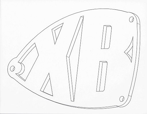
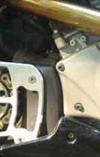
So ive been looking around online and found out how cool custom sprocket covers look on our bikes and stuff. so i thought i can i can make one of my own and try it out. i am handy with autocad so i started just messing around and seeing what i can put together. so let me know how u guys like it because im going to get it one cut out for me soon and if anyone is interested let me know and i can figure out a price. but more important let me know how u guys like them. this is the drawing in 3d. hopefully when its cut it will look like that. and yes it is all drawn out to scale for our bikes. but i have one question are all the sprocket covers the same distance from holes on all the years of the bikes. this one is from mine which is in 03.  | ||
Skinstains |
Looks neat but I think you are going to need standoffs or spacers behind it. I have always been partial to the flying horse myself. | ||
Migs16 |
well ya im gona buy spacers and all of that. thats the easy part. | ||
1_mike |
So...you like that word don't you..... For my two cents, make something that is consistent. That is, 1. you have a triangle with two curved sides, off center of the plate. 2. You have two "D" shaped slots. 3. You have a long thin triangle 4. You have two pumpkin eyes...or even different shaped triangles. 5. An "odd" shaped hole with the "boss" off-center of the mounting hole and it also has two different outer diameters....! Also the point of the "triangle" is off center of the plate. 6. you have a partial "boss" on the two front mounting holes that don't need to be there. Just make the outer edge .03" farther out. Again, just my two cents. Mike | ||
Migs16 |
hey man first off this is not a front shot its an angled shot. second its a first drawing that isnt anything for sure. i do have some touching up to do everytime i look at it. soo thanks for ur 2 cents cause soon im gona turn them into alot! | ||
Cycleaddict |
i like it ! , black anodised alum. or some sort of plastic, abs. etc.(1/4"thick) would work nicely | ||
Migs16 |
ya im gona get in cut in aluminum and then get in powder coated orange or black not sure yet. thanks though! | ||
Glitch |
I like it! | ||
Gentleman_jon |
I like the idea a lot. Very clever the way the X and B are used. I do hope you will take no offense if I make two modest suggestions. I. Perhaps the design would be more in keeping with the proportions of other parts on the bike if the X and the B were just a little lighter in weight. 2. This type of plate leaves the electric connectors out in the weather, for which they were not designed. I solved this problem by using a cut down piece from the original plastic cover over them.  | ||
Migs16 |
ohh hmm yes thats a good idea about covering the electrical. once i get it cut out im going to see how my electrical is and may i can use the original plastic like u said. Thanks! | ||
Ratfink |
I'd love to get in with this if you give it a go. Only thing I would like to see different is no need for spacers. Isn't there a way to incorporate spacers into the design? | ||
Migs16 |
as of now i was just going to go to orchards and buy some for cheap. but i was kinda thinking of trying to sketch them in but i would have to weld them on and that would add to the weight and stuff so im just going to leave them with the spacers. thanks for the in put. | ||
Jake318 |
Looks great, your artistic skills are head and shoulders above my own lol. | ||
Mark_1 |
Very nice | ||
Ericz |
Migs-- Just one suggestion from a manufacturing stand point. 1. If you are going to have it machined from aluminum, try to eliminate any of the sharp inside corners. Common endmills that are used to cut out such a piece quickly(ie cost effective) are kept around 1/8" in diameter or larger. The sharper the inside corners, the smaller the endmill and the slower it machines/costs more. It would be a different story if you want them to be cut out on a waterjet but that depends on the shop you contract with. | ||
Migs16 |
i was thinking of using a plasma cutter. my school have the computer hooked up to it. but thanks alot for the heads up with that. | ||
Welderjosh |
I have done a lot of CNC plasma. You are going to lose a lot of detail in the corners on a piece this small. It will look ok, but a laser will tighten it up a lot. | ||
Greg_e |
This is a job for waterjet. That said if using a milling machine I would drill the "sharp" corners with a 1/32 or 1/16 bit and then mill into the hole. I've done other things like this and it leaves a very "square" corner for my desires. The triangular corners are just going to have to be what they are with this method, not going to be sharp unless you go to really small drills and step your way back out and finish with a file to clean things up. After that a CNC should be able to make easy work out of the design. |