| Author | Message | ||
Hildstrom |
  | ||
Posplayr |
Hildstrom: There is also Shunting going on as the duty cycle of the Battery charging phase is modulated as well. On older SCR type SHUNT R/R's I have measured changes in dutycycle as funtion of RPM. | ||
Timebandit |
Greg, you have a valid question about the circled voltage at 2k RPM. I share your concerns. In interpreting that data, I followed accepted engineering principles. Because the chart that Pos had offered allegedly represented the analysis of a regulator, then terms such as V-in and V-out should represent the input and output voltages for the regulator, not for some other piece of hardware. If the circled value that Pos has labeled as "Vout" actually represents the input voltage to the regulator, rather than the output voltage to the battery, then the chart is mislabeled. I trusted him to accurately describe his data, and in trusting him to label everything accurately, maybe I screwed up. When I asked Pos to clarify everything before we got started with the analysis, he responded to the effect that "we'll just use accepted engineering principles." OK then: According to accepted engineering principles: when you're creating a pictogram that demonstrates the activity of a series regulator, you need to label your chart legends appropriately. Specifically, V-in should refer to the voltage INPUT to the regulator, and V-out should refer to the voltage OUTPUT of the regulator. If you don't do that, then you're not following accepted engineering principles. This is particularly important, because the appropriate analysis of a regulator REQUIRES us to look at the actual waveform of Vout (from the regulator to the battery) to determine precisely whether or not regulation is taking place. Unfortunately, Pos' data fails to provide any traces that demonstrate the Compufire's output to the battery. I was hoping that at least he'd give us a numerical answer, if not an actual trace, to facilitate an accurate analysis. If your assertion is right, and what he's labelled as �Vout� is not a true representation of Vout, then he has failed to give us ANY useable data about the output from the Compufire, which renders his entire PDF pretty to look at, but pretty meaningless as far as accurate data analysis is concerned. In making the decision to withhold all information about battery (output) voltages, he has reduced anyone's ability to analyze the data to the point that we are forced to make best guesses about what's happening with those voltages, and when regulation is actually taking place. By leaving out a key piece of the puzzle -- voltage output to the battery -- the analysis of what is actually happening at each RPM becomes quite difficult. If you're right, and what he labels as �Vout� in his chart does not represent Vout from the regulator, then Pos has posted an inconclusive set of data, and exact interpretation becomes impossible. I was just doing the best job that I could do with the data that was made available. If the complaint involves a lack of quality in the data, the responsibility for getting that right falls upon Pos. Now here's the kicker: It doesn't even matter whether or not Vout in the 2k RPM chart represents the regulator input voltage or the regulator output voltage. Whether that is actually Vin or Vout, the change in nomenclature won't effect the results of the analysis for deployment of the CF on Buell 1125 motorcycles. There are a number of reasons for this: 1. Right now we're quibbling about whether or not the data tells us that a Suzuki can regulate at 1k5 or 2k RPM. Whether or not a Suzuki stator is hot enough to provide enough "juice" to regulate at 2k is immaterial to our Buell application. What matters to us is whether or not an 1125 with the 2009/10 stator makes enough juice to regulate at idle or at 2k RPM. Quibbling about what is circled on the chart won't change that result. 2. H-D/BMC revised the charging system in 2009 to cure the �problem� with the 2008 charging system, which had insufficient output to charge at idle. According to H-D, our bikes make enough power to regulate and charge at idle. 3. Point 2, that our bikes make enough power to regulate at idle, is substantiated by everyone's real-world experience that a properly functioning 2009 1125 charging system can produce over 14V of Vbatt at idle and keep the battery charged. Of course you'll agree on this point, because your own set of data from your stator rewind thread clearly shows that. With my totally stock setup, I never fall below 14.2V at idle after a few miles or riding, even with a mildly higher system load (bright lights on). 4. Nightsky has already shared data that shows that the 2009 1125 charging system makes enough power to regulate and charge AT IDLE. It really doesn't matter what the Suzuki does, we aren't riding Suzukis. The facts are that the 1125 with the stock Ducati shunt regulator produces plenty of excess power to charge the bike at idle. For an 1125, Vout (or Vin if you want to call it that) is a voltage that is adequate to allow regulation. What's circled in red on the 2k Suzuki plot doesn't really effect us. 5. Regardless of whether or not �Vout� is adequate in that one diagram for the Shindengen regulator on the Suzuki, we see that the SHAPE of the waveforms NEVER CHANGES in any of the Shindengen regulator traces, all the way from 1500 to 5000 RPM. Everyone knows that the Shindengen shunt regulator DOES regulate long before the bike reaches 5000 RPM. There are people riding with the Shindengen regulators who routinely keep the bike's RPM below 5000 RPM and the Shindengen keeps their battery charged. 6. Pos' own criteria for determining whether shunt regulation is taking place says that �waveform comparison� provides the answer. Using his waveform analysis criterion, the Shindengen regulator's waveform traces look the same at all RPM values from 1500 to 5000 RPM. We know from real-world experience that our bikes regulate well before 4000 or 5000 RPM. According to Pos' own definition, regulation has to be taking place at 2k RPM in these charts, because the 2k waveforms are identical to those produced at 5000 RPM when regulation is known to be occurring. 7. In the big scheme of things, quibbling over the definitions of shunt regulation doesn't change the final outcome. The actual method by which the stator is controlled is immaterial. What matters, and only what matters as far as stator life is concerned, is the reduction in duty cycle of the stator. The means of controlling the stator are immaterial to the ends that are achieved in controlling it. The bottom line is that the amount of duty-cycle reduction is what is going to prolong stator life. Period. Pos own data show that in the RPM ranges in which our stators are at-risk, the Compufire is capable of limiting the duty-cycle of the stator by up to 50%. That could provide a 50% reduction in power dissipation in the stator, but if and only if you operate at system loads that are low enough to allow such duty cycle reduction to occur. Ride with higher loads and those �savings� go out the window. Now, I will freely admit that the Compfire's ability to potentially reduce stator duty-cyle to 50% under low load conditions is impressive. That will prolong stator life. As a generic product marketed for many makes of bikes, it's a good thing. But as a Buell-specific product, it doesn't bring anything new or meaningful to the table for 1125 owners who already have the H-D relay harness. Why? Because the CF's amount of duty-cycle reduction just does't amount to the same level of protection that the H-D relay harness offers; The H-D relay harness provides a reduction in duty cycle to 33% by single phasing the output. Reduction from 100% duty cycle to 33% duty cycle represents a 66% decrease, which is better than the 50% offered by Compufire. The simple math tells us that H-D wins and CF loses.
That's not quite what I said. I said that I am looking at the regulator as a black box, not knowing what is inside, and that I am only left to look at Pos data and draw conclusions from it. Using the black-box model, I am barred from speculating too much about the actual circuit implementation. Pos own set of data provides such perfect square waves and sine waves that it suggests that the mechanism in which CF implemented �series� regulation appears to be no more complicated than putting a switch (pass transistor) in series with a shunt regulator to synchronously control it's duty cycle by modulating the shunt regulator's Ton and Toff. According to the many definitions of �series� regulators that have been offered in this thread, that method would be the simplest one to implement. I agree that key pieces of data (Vbatt tracings as a function of time) have been withheld, and that such withholding prevents anyone to conclusively prove whether this hypothesis is correct, or whether an alternate hypothesis may be correct. The problem is that we don't have that data, and we're forced to limit the conclusions that we can draw to the data that has been presented. The data set that lies before us does not provide enough information to conclusively refute my conclusions in favor of another theory. Now about those waveforms. I find them interesting. I've hooked up oscilloscopes to a lot of charging systems in my day, and I've never seen any real world charging system that produces such perfect square waves and sine waves. In the real world the traces provided by these devices are not as perfect as they would be if someone modelled the math from an IEEE paper and plotted the results. Hook up a charging system in the real world, and the tops of those square waves DO get rounded, just as Nighsky suggested they should be. And the current waveforms are not perfect sine waves, for a number of reasons. But that's a huge can of worms that I really don't want to open. The bottom line is that Duty Cycle defines the answer for us. (Message edited by timebandit on June 12, 2012) | ||
Timebandit |
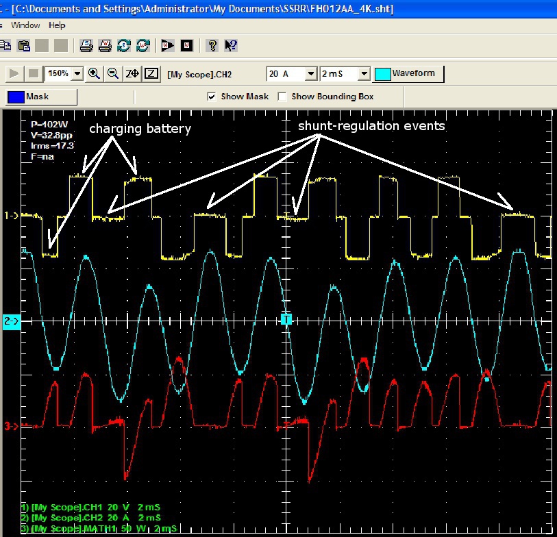
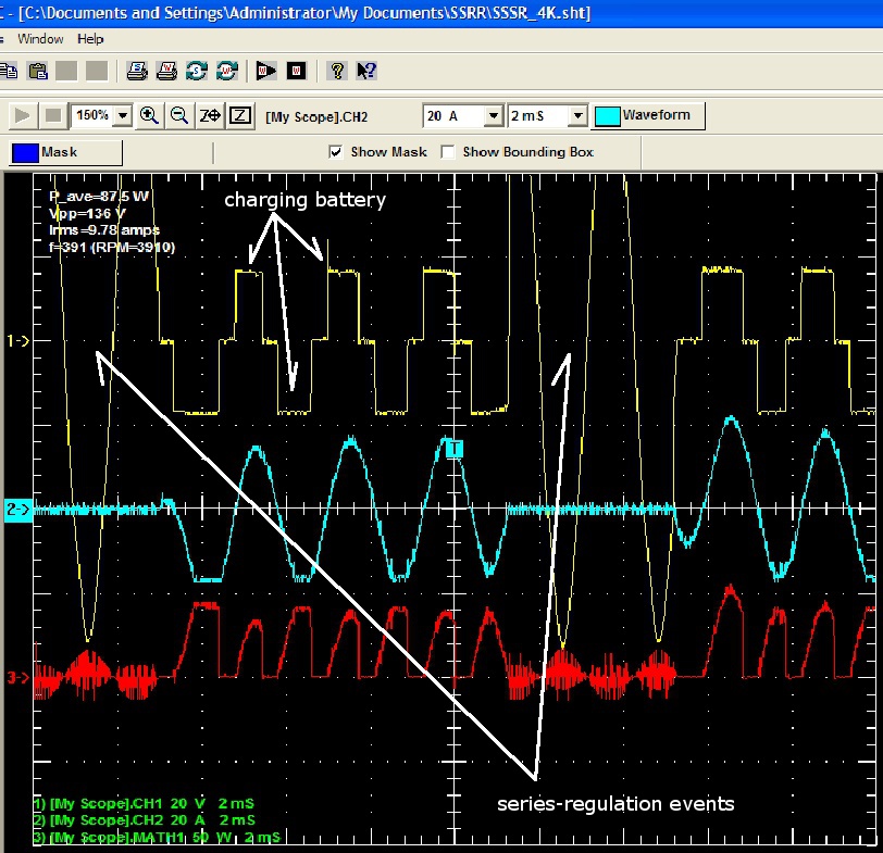
I take issue with Greg's plots that suggest that "series regulation events" are confined to those areas on the chart indicated by the arrows. That is just not correct. They are every bit as wrong as Pos' assertions that "regulation occurs here." During those periods marked by arrows, all current flow is shut off, and NOTHING is happening but the passage of time. What Greg is labelling as "series regulation events" are actually only a subset of the total number of series regulation events. Specifically, the items that Greg has labelled as "series regulation events" that are occurring when no current is being passed (flat blue traces) comprise what is accurately described as the "T-off subset." By definition, all of the events that occur during all portions on the graph represent the total superset of series regulation events. That superset is then divided into T-on and T-off subsets, and the ratio of T-on to T-total (T-total = T-on + T-off) is how the Duty Cycle of the stator is defined. If you look at the situation using accepted engineering terminology, all of those waveforms that correspond to passage of current (blue sine waves) comprise the T-on component of series regulation events, and all of those waveforms that correspond to periods in which passage of current is interrupted (flat blue traces) comprise the T-off component of series regulation events. Series regulation is defined by varying the ratio of T-on to T-total. It is not defined by pointing at T-off. (Message edited by timebandit on June 12, 2012) | ||
Sprintst |
Okay, instead of a pissing contest over what the charts mean, how about putting your money where your mouth is folks? Back up your products with a warranty that pays out if the regulator doesn't do it's job and the stator fails. Who will be the first to step up?  | ||
Timebandit |
Good point, Sprint. That's where the rubber meets the road, isn't it? We all know which manufacturer has refused to provide warranty of their products in a Buell application. | ||
Kenm123t |
I have been following this thread for a while now. The way to increase stator life is keeping the temperature in the stator as cool as possible. The 1125r and similar bikes with wide rpm bands a heavy low speed loads (fans lights fuel pumps Ecms and in Froggys case about 5 laptops) should have automotive type alternator or a brushless generator to control the out put with lower internal heat build up Shunting the output to ground is nothing more than shorting it to ground and hoping the stator does not over heat and burn out within the warranty The reason some people have good results with the relay is that you have a one in three chance of shutting down the phase winding that overheats. lack of oil flow and the wiring loom with its over generous packing of RTV further limits the cooling of the affected phase. The practical limit on motor or alternator output is cooling. Hermetic refrigeration motors are cooled with cold return vapor or by direct liquid refrigerant injection. Mitsubishi's typical powerplant alternator stator is watercooled. Duty cycling with the relay added only reduces the load on part of the alternator If your lucky the relay kit will shutdown the winding thats buried under the rtv and wiring loom which also gets the least cooling oil at low rpms. The Compufire is the better solution since you duty cycle the entire stator not just 1/3rd of it two windings are still in use even in single phase operation. When rewinding a stator install a motor winding over load with a temp rating compatible with the insulation of the wire. The temp overload will cycle and prevent a burnout and reset hopefully before the battery runs down. Letting it cool would allow you to get home after a overheating event. Looking at the compufire square wave outputs they resemble older low baud rate IGBTs from analog drives and or chopper diode drives Graham (now Danfoss) built 20 + years ago With out wiring and or a battery connected capacitance is low so a sharper wave form is to be expected. Short quick fix there isnt one Rotax and other M/C companies need to design better alternators. Rotax through OMC builds water cooled alternators for Evinrude/Johnson outboards. For the 1125s adding the cooling port to the rotor with a relay or a Compufire will prolong alternator life as will using the 2008 charging system. | ||
Timebandit |
The ultimate responsibility for the stator problem falls on Rotax; it's their engine design, they are the people who decided not to put the hole in the rotor, and they are the people who profit from replacement stator sales. Everyone here should be smart enough to realize that they did this on purpose to make a killing in selling replacement parts. Or if you want to blame Buell, you can blame BMC for letting the Rotax design go to production without modifications. Not that that is a big deal -- new models often have bugs that take a year or two to get stomped out. Unfortunately, H-D shuttered BMC before the fix could happen. Well, EBR has come along with the fix. Problem solved. On the subject of when cooling is better and when duty-cycle is better: your 1/3 chance of getting the right coil is wrong. Single phasing takes out 2/3 of the coils, so it's actually a 2/3 chance. If 2/3 isn't good enough for you, and you want to be absolutely sure that you interrupt the right lead, then just bundle a wire around coil #1 and measure induced voltage as you pulse some voltage through the stator coils. Then identify exactly which lead needs to be interrupted to protect coil #1. Implementing a permanent solution where the harness realy always shuts down the proper lead becomes as simple as moving the pins in the stator connector. That's what I did. I can guarantee with 100% certainty that when my relay harness triggers, coil #1 is being turned off. | ||
Timebandit |
As far as the relative contributions of the different cooling methods are concerned, consider this: Hildstrom's latest set of published data for temperature on his rides following the rotor rewind shows some interesting results. the data clearly demonstrates that even with the CE series regulator, the 1125 stator accumulates heat at low RPM, and but at high RPM and high speed the stator temperature actually falls. No surprises there -- we all know that RPM and MPH together are what cools the stator, and that lack thereof is what makes it hot. What's interesting is that the risk to the stator (heat accumulation) on a bike wearing the CE series regulator occurs at RPMs below 4000, and that at RPMs above 4000 that are accompanied by highway speeds, the stator temperature becomes stabilized and or reduced. You'll have to look at his charts with a critical eye to see this -- it's something that's obvious in his data, even though he has never described the observation. This clearly tells us that the at-risk period for the stator is during operation below 4000 RPM. What a coincidence, that's exactly where the H-D relay harness is designed to operate. Maybe, just maybe, those engineers at H-D know EXACTLY what they are doing. Going one step further, his data shows that even when using the CE series regulator, the steepest slopes in the stator's heat accumulation occur at idle and below 4000 RPM. That very clearly demonstrates that the CE regulator isn't helping (helping enough?) in the range below 4000 RPM. That's the range in which the H-D relay harness operates. Of course, the H-D relay harness doesn't do squat below 2000 RPM. But then POS' data shows that his Compufire regulator doesn't do squat to cool the stator below 2000 RPM either because it keeps the duty cycle at 100%. What's the obvious answer? It doesn't take a rocket surgeon to understand that in the area of highest thermal risk to the stator, which is 4000 RPM and below, none of what we're loosely describing as "series" regulators offer help in the most dangerous part of the risk zone, below 2000 RPM. Prolonged idling is the most dangerous thing that you can do to the stator. There is one and only one product that can possibly help to improve the situation below 2000 RPM. It's not the relay harness. It's not the CE regulator, and it's not the CF regulator. The only device that can help where we need it most -- AT IDLE -- is the oiling rotor. If you guys want to do the most that you can to cool the stator, the simple answer is not to operate it in a range in which it is unprotected. Better yet, install something that will protect it across the entire powerband and at every load level. The oiling rotor is the only device that fits the bill. Then, when it comes to choosing the next layer of protection that you want to add, you need to look at the duty cycle reduction that's caused by the different "series" regulators. Starting at 2000 RPM, the H-D harness immediately gives you a 66% reduction. At 2000 RPM, the Compufire is skipping on 1 in 5 pulses, resulting in an 80% duty cycle. Compare that to the relay harness' duty cycle of 33%. Relay harness looks better ... especially if you know which leg to deactivate using the methods i've described above. At 4000 RPM it looks like the CF is skipping on maybe 7 of 18 cycles, which corresponds to a 61% duty cycle. Compare that to the relay harness' duty cycle of 33%. Relay harness looks better ... especially if you are disconnecting the troublesome leg. Beyond 4000 RPM the CF's duty cycle reduces to perhaps 50%, but Hildstrom's data says that the MPH and RPM are adequate to prevent heat accumulation in the stator -- above 4000 RPM the stator temperature stops climbing, and may even decrease, depending on your exact speeds. What I see in the data is that at all times that are material, the HD harness is reducing duty cycle twice as much as the Compufire, and that neither the Compufire nor the Harness help you below 2k, where the problem is worst. That tells me, plain and simple, that the first place you want to spend $200 is on the oiling rotor. It should be considered as your primary means of protection, and everything else should be considered as supplemental protection that can be added at your discretion. Buy a CF if you really want to, but there's no logical reason to make it your first $200 expenditure. (Message edited by timebandit on June 13, 2012) | ||
Nightsky |
These scope shots were taken on a Buell 2009 across one stator leg with the ducati regulator operating. 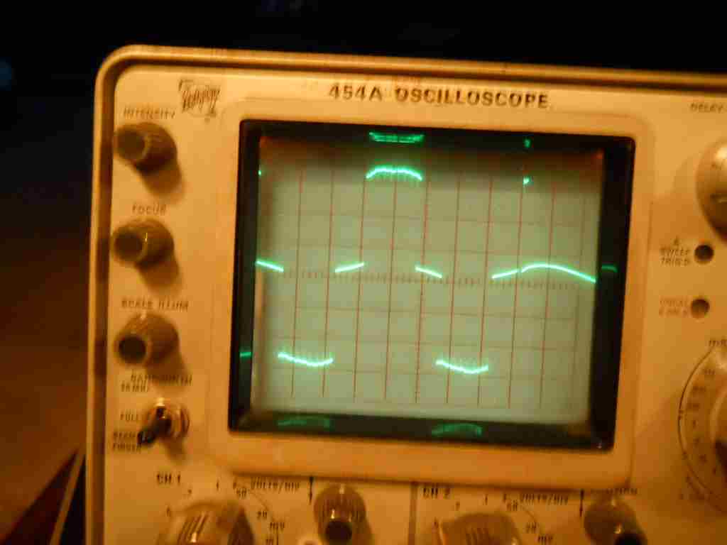 Stator voltage with Ducati vreg, 1.5kRPM, 5Vdiv, 2msdiv. See the rounded tops I would expect on real data? The stator dumping current into the battery raises battery voltage and rectifier drop. It's near the peak of the sine wave hump. Also, the zero volt level has pronounced slope as you would expect on real data. The equations in the paper only approximate the flat areas and that works well for their calculations. The stator inductance swings against the battery to maintain constant inductor current, and sometimes the other two windings subtract to yield zero volts across the measured winding. On the right can be seen the shunt regulator clamping to ground. It does not appear that the Ducati shunt reg clamps to 14.0V. It clamps to 0V. 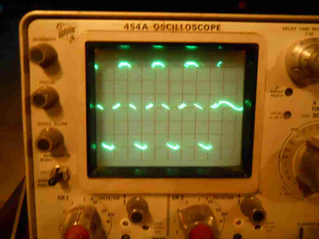 Stator voltage with Ducati vreg, 3.2kRPM, 5Vdiv, 2msdiv. Again we see tops are not flat on real measurements from peak current, and neither is the 0V area. Battery voltage isn't really constant. For example, an unloaded lead acid battery measures about 12.7V and has internal resistance. Charging is typically done between 13.6V and 14.0V. The battery is only a perfect voltage source on paper. The Tektronix 454A has 150MHz BW, and the 10x probes are 250MHz BW. | ||
Hildstrom |
There is some evidence of the rounded corners and sloped zeroes in Posplayr's graphs, but not much. Your analog traces are very smooth. I wonder if Posplayr's digital scope was not precise enough (not enough bits) or not stable enough to reliably observe that effect. | ||
Alaskacr |
Probe compensation adjustment can make those rounded corners appear/disappear. Scope operators must ensure to "cal" probes before use. Not saying that is or is not the issue here, just pointing out it can square-up/round-off/ or cause overshoot to appear. | ||
Posplayr |
I think Nightsky's scope has some calibration issues. I did these measurements back in early 2009 and some some variation from flat top depending upon RPM and probably battery charge. At that time I was quantifying how the SHUNT R/R's firing angle control which effects ON duty cycle related to RPM. If you look closely you will see the difference in voltage drops due to a full wave diode bridge in the SCR SHUNT v.s. the the MOSFET R/R which only has the upper 1/2 of teh diode bridge. The SCR's are and lower 1/2 of the diode bridge are replaced with MOSFETS in the FH012A. That was the basis for the power comparision. http://www.keepandshare.com/doc/4143240/scr-mosfet -shunt-compare-pdf-june-14-2012-12-34-pm-905k?da=y | ||
Nightsky |
  | ||
Posplayr |
Nightsky: It looks more like a grounding issue. The THS730A is a battery operated device and is probably better isolated from the 120V power. That 454A is a bench scope and probably grounded to your 120V plug. I wonder if you ran a (fused just in case) ground wire from the frame of the motorcycle to the ground plug on your 454A power outlet it would go away? (Message edited by posplayr on June 16, 2012) | ||
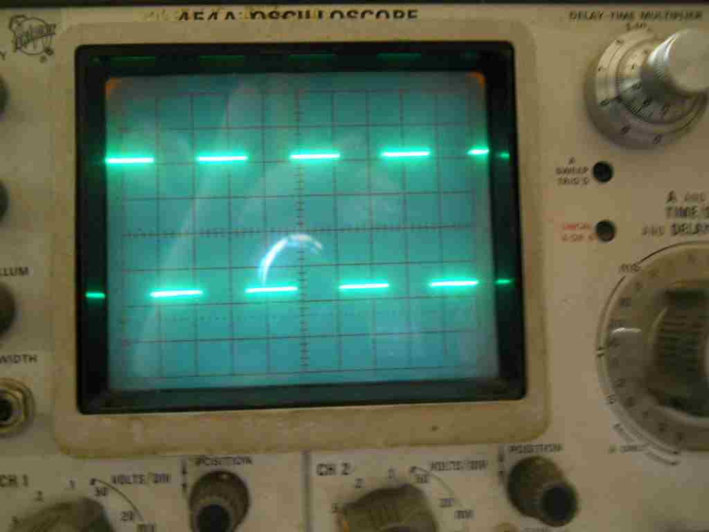
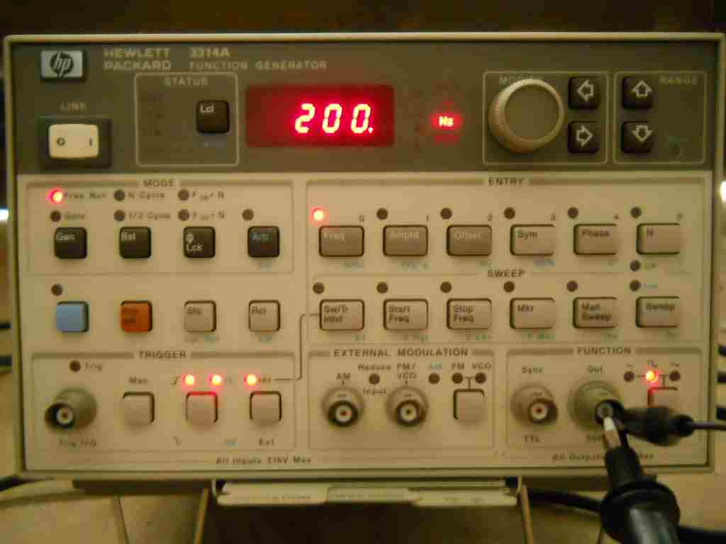
Timebandit |
Somebody's tracings don't look real to me. I was going to pull out my garage scope this weekend and take some snapshots of the screen traces to provide verification of what "real world data" looks like on an oscilloscope. I won't be able to do that for at least a couple more days because my bike is apart right now; I just repainted my OEM exhaust and the paint is going to take 48 hours to cure. As far as the data that's been posted to this thread is concerned: Pos' brings up the issue of calibration, accusing Nightsky's scope of being mis-calibrated. Although Pos' own data has never been accompanied by verification of calibration, he has accused Nightsky of having a mis-calibrated scope. Nightsky responded by providing verification of calibration data for his scope, something that Pos hasn't yet done. Nightsky took a very expensive HP 3314A signal generator and fed a pure square wave test signal to his Tek 454A scope. The scope responded by drawing perfect square waves with a flat baseline. What this tells us is that Nightsky's scope/probes are properly tuned; there is no mis-calibration of the probe that could have induced the round-tops and undulating baselines. The calibration traces also verifies that Nightsky's scope DOES have the resolution to accurately trace a high frequency square wave, and that the arched-top waveforms and undulating baselines in his photographs are *REAL*. We know that they're real, because you can't FAKE on-screen data using an analog scope. Unlike a PC charting program, which will plot whatever data you give it, Nightsky's analog Tek scope can only trace a real-time voltage source that it's actually hooked up to. Nightsky's last set of pics removes all doubt that the observations of round-topped waves and undulating baselines in what Nightsky calls "real" data were caused by a mis-calibrated oscilloscope, or that they could have been generated using faked data. A different hypothesis is now required if anyone wants to discredit Nightsky's observations that the real-world data is NEVER flat-topped or flat-bottomed. Now Pos is suggesting a new hypothesis to discredit Nightky's observations -- namely, that the scope has a grounding issue and is picking up interference from 60-cycle line power. Notice that Nightsky's scope tracings identify that the time base for the traces are 2 milliseconds per division. At 2 msec/div, or 0.002 seconds/division, a 60-Hz sine wave that's caused by noise from the AC power line would require 8 divisions to trace: Divisions = 1 division/0.002 sec x 1 second/60 cycles = 8 The math tells us that if Nightsky's data were corrupted by 60-cycle noise, that 60-cycle sine wave would occupy 8 divisions on the oscilloscope screen. The fact that there is no on-screen interference that spans 8 divisions tells us without any doubt that AC line noise isn't causing what's observed in the scope tracings. Going further, the questionable waveforms speed-up synchronously he stator speed as the bike's RPM increases. Line noise can't do that. This is CLEARLY not 60-Hz AC noise. It's time for a new hypothesis. | ||
Timebandit |
Oops. That last paragraph should have ended with this: "Going further, the questionable waveforms speed-up synchronously with the stator speed as the bike's RPM increases. Line noise can't do that." | ||
Posplayr |
Bubba, I'm both stupefied and amazed by the brilliance. NOT POS | ||
Timebandit |
In other words, you are at a loss to explain why real-world, un-fabricated data doesn't look anything like your data. | ||
Nightsky |
60 cycle hum on the waves would show up with the bike off. Bike off, my scope trace is flat. Slopes on crossings and humped tops are synchronous with stator frequency, so they are part of the Buell 2009 waveform. | ||
Posplayr |
In other words, you are at a loss to explain why real-world, un-fabricated data doesn't look anything like your data Bubba, Is this the same fabricated data you did your brilliant analysis of? Yea the analysis that proves SERIES is no better than SHUNT regulation? I am at a loss Geeeez  ; u never heard of a ground loop? The bike and the scope are not at the same ground reference unless Nightsky is running some steel tires. | ||
Timebandit |
You are not being accurate or honest. I did not ever say that series regulation was no better than shunt regulation. What I said was that using the same definition of reduction in duty-cycle that you were using to promote the Compufire product, the OEM shunt regulator plus charging harness update provides more duty cycle reduction (and more protection) than the product you are recommending. Your attempt to twist these words to imply that I said that "SERIES is no better than SHUNT regulation" is a totally dishonest statement, and a purposeful misinterpretation of the facts. You are now telling outright lies. | ||
Nightsky |
Nope. No ground loops. Scope chassis is floating from AC ground. Bike is directly grounded to scope. What is the exact connection configuration between your bike and your scope? (Message edited by Nightsky on June 19, 2012) | ||
Hildstrom |
Timebandit: "What I said was that using the same definition of reduction in duty-cycle that you were using to promote the Compufire product, the OEM shunt regulator plus charging harness update provides more duty cycle reduction (and more protection) than the product you are recommending." Don't those claims depend on the operating conditions of the bike and on a lot more data we don't have? Both approaches need to keep the battery charged enough to keep the bike running. If you are at idle/low/<2000 rpm with both cooling fans running at full blast long enough, neither approach going to reduce duty cycle or stator current. I think you mentioned something like that in an earlier post. In the duty cycle analysis for 4000rpm above, you assume the harness open-circuits a leg (33%) and never closes the circuit again. If the bike were run under those conditions long enough, wouldn't the ECM eventually close the relay for a while so the battery could be kept charged? (Not trying to be annoying, just asking a real question.) I think the average harness duty cycle would approach what is observed with a series regulator because the same average current is needed by the battery/fans/ecm/lights/etc. Under conditions where the harness does nothing, the series regulator continues to reduce duty-cycle/current/heat in the stator compared to the stock shunt regulator. I woudn't overlook this effect. If the stator is at a lower temperature when you're blasting through the twisties at high rpm, it will have a lower starting temperature when you pull up to the next traffic light. | ||
Posplayr |
Nightsky, Using P6117 200 Mhz 10x Passive Probes that came with the THS730A and the optional A622 Current Probe (AC/DC 100 kHz clamp). The THS730A is normally battery operated but I have it connected to an AC power adapter and a laptop via RS-232 (from the same power strip). Either both probes or a probe and clamp is operating at any one time. Leg to leg measurements are probe and ground clipped to the legs. Leg to round has the ground clip clipped to a frame ground. A picture was provided in one of the powerpoint presentations. | ||
Timebandit |
"If the bike were run under those conditions long enough, wouldn't the ECM eventually close the relay for a while so the battery could be kept charged? (Not trying to be annoying, just asking a real question.) I think the average harness duty cycle would approach what is observed with a series regulator because the same average current is needed by the battery/fans/ecm/lights/etc." You may be right on that. If you time-averaged the data long enough, the ECM's assessment of the battery state could eventually bring the duty cycle up to whatever is adequate to keep the battery's charge state optimized. Under that condition, the duty-cyle of the stator/harness system could rise to the point that it's duty-cyle would be equal to any other series regulator that bases it's activity on the same criterion. That would be an interesting set of data to collect. Keeping this in perspective, maybe the best way to phrase the conclusion would be: "Using the same definition of reduction in duty-cycle that you were using to promote the Compufire product, the OEM shunt regulator plus charging harness update provides an equivalent amount of duty cycle reduction than the product you are recommending ... and it's FREE." | ||
Timebandit |
"Under conditions where the harness does nothing, the series regulator continues to reduce duty-cycle/current/heat in the stator compared to the stock shunt regulator." If you're willing to base an analysis upon that premise, it's not possible to reach anything but a biased conclusion. It's not really a question of whether or not a series regulator reduces heat compared to a shunt regulator. We already know the answer. To be objective, you need to look at the bike in the condition that it has been supplied to us by the factory: it already has a series regulator, embodied in the form of an ECM controlled switch that modulates the duty cycle of the shunt regulator. Everyone owns a bike that has that equipment on it (or has removed that equipment). That's our starting point. The question now becomes: I have $200 to spend on upgrades to the bike. How should I spend that $200 to get the most bang for the buck? The answer is not going to be to spend that $200 to replace one series regulator with a different series regulator, because doing that doesn't result in a net improvement in your situation. You pointed in your last post that in the long run, both series regulator embodiments might offer the same level of protection. A problem remains though, that neither series regulator provides any benefit at low RPM where the heat problem is at it's worst. The best answer for that problem is going to be to spend that $200 on an oil cooling rotor that will help cool the stator at all RPM, in addition to having some sort of implementation of a series regulator that can reduce duty cycle. I think that the combination of the oiling rotor plus some form of series regulator is the best solution that's available right now. Assuming that everyone already has some form of a series regulator on their bike (it was provided by the factory), it makes far more sense to spend the next $200 to buy a new, complimentary form of protection, and add a layer of protection that employs a method that's different from what you are already using. | ||
Dannybuell |
If as I have learned in these posts the harness relay is a POS and burns out too frequently, wouldn't it make sense to transfer this responsibility to a non ECM based voltage regulator? Is there a better relay than the Bosch(?) type that won't burn out? | ||
Posplayr |
Dannybuell: I strongly suspect the harness relay saves one set of windings while putting additional thermal stress on the other two. The current from the stator is limited by the magnetic flux the rotor can support. So at a high enough RPM, even if your open one of the legs the total current out of the R/R will be the same. However that total current is now being generated by one pair of windings rather than being shared by all three. The relay mod is a HACK by someone that probably never measured the stator currents. A SERIES R/R with a balanced control will open and close the three windings with equal frequency distributing the stators thermal load uniformly. (Message edited by posplayr on June 19, 2012) | ||
Baf |
The harness allows battery voltage to sag quite low, in my experience. So if the series regulator and shunt w/ harness achieve similar stator protection, then I'd rather have the series reg. No pesky relays to fail, no worries about stressing the battery and having the fans run slower due to the lower voltage, etc |