| Author |
Message |
    
Reepicheep
| | Posted on Thursday, May 10, 2012 - 09:06 am: | 


|
Thanks for putting in all that time TimeBandit, that was a really thoughtful and clear explanation. |
    
Sparky
| | Posted on Thursday, May 10, 2012 - 02:15 pm: | 


|
OK, I understand completely the three circuit loops in the diagram. Thank you for highlighting those making it clearer to identify especially the last one, circuit BC.
I still think you are drawing the wrong conclusion though. Have patience and see if the following makes sense.
The point I've been trying to make regarding that last circuit is this: Yes it is one circuit but it contains two voltage producing sets of coils.
When the B phase/coils produce voltage, the positive current flows to & from the VR in a clockwise direction, back to the B coil common point thru the C coils.
When the C phase/coils produce voltage, the positive current flows to & from the VR in a counter-clockwise direction, back to the C coil common point thru the B coils.
Thus the two sets of coils should produce two pulses of current for each revolution, should it not?
TimeBandit, if I'm wrong with this explanation, I apologize, and won't take any more of your time. Anyway, this theory explains why I had a hard time accepting your "single-phasing' theory when the relay open-circuits its one phase wire. |
    
Hildstrom
| | Posted on Thursday, May 10, 2012 - 03:40 pm: | 


|
Sparky: When all three lines are connected to the VR, the current through phase B is a function of both the AB and BC circuits. Likewise, the current through phase C is a function of both the AC and BC circuits. If line A is disconnected, there is no current flowing through phase A and the current in phases B and C is a function of the BC circuit only. Yes current continues to flow through two phases B and C, but it is less current than if line A were also connected.
I find this harness open-circuit situation much easier to visualize as the actual Delta configuration. This page does a good job of explaining why current does not flow inside a Delta configuration when no loads are connected. Once you accept that and disconnect line A, it is much easier to visualize 2/3 of the stator not being used.

|
    
Timebandit
| | Posted on Thursday, May 10, 2012 - 04:52 pm: | 


|
edit: I started writing this before Greg posted his helpful post above. I tried to find that same page on 3-phase power that Greg linked, but for some reason I wasn't able to find it using that site's search box, which left me to use the PDF link below. thanks, Greg. 
We're going to have a problem, because our discussion is going to focus on explaining theory based upon an over-simplified schematic that does not accurately portray the behavior of the real-world physical stator; this creates fertile ground for making over-simplified statements that result in miscommunication and misinterpretation.
I think some of your comments, Sparky, are based upon a hybrid of conceptualizing what's shown in the schematic, and injecting some of your knowledge of the pole behavior in the physical object, and you're blurring the distinction between the two. What we call "coils" in the simplified schematic diagram are not the same thing that we refer to as "coils" or "poles" in the physical layout.
Part of the problem is that the imaginary "coil" that's depicted in a simplified Wye schematic diagram doesn't correspond with the real-world definition of "coils", or more accurately "poles" in the physical object. In the schematic, what looks like a single "coil" actually represents a population of "poles" in the physical object. By making an over-simplified explanation based upon the over-simplified schematic, I just know that I'm sticking my neck out and putting myself at risk for a power engineer to come along and point out a problem with the over-simplified explanation. When that happens, there goes my credibility. The problem is that I just can't water this stuff down to make it understandable to the average non-engineer riding a motorcycle without losing some of the accuracy in the content. If anyone really wants to understand 3-phase power then they need to take a 3-phase power course and not look for a spoon-fed simple explanation here. I think we're already pushing the limits of what's reasonable to discuss on a non-engineering internet forum.
With that caveat in place:
"Yes it is one circuit but it contains two voltage producing sets of coils."
No, it doesn't really contain two sets of voltage producing coils. The wires of B and C are joined together at the vertex of the Y so that they are wired in series. In the Wye configuration schematic diagram, B+C acts as one coil whose inductance is the sum of the inductance of each individual coil; an analogy that might be more familiar would be two resistors that are wired in series and act as one resistor whose resistance value is the sum of the individual parts.
"When the B phase/coils produce voltage, the positive current flows to & from the VR in a clockwise direction, back to the B coil common point thru the C coils."
In the schematic, the coil set comprised of B+C should be conceptualized as one coil set BC which acts in unison because the two coils are corrected in series. Whether or not output voltage is positive or negative depends upon whether the north or south pole of a magnet in the rotor is passing over the pole in the stator.
"Thus the two sets of coils should produce two pulses of current for each revolution, should it not?"
Well, not exactly. In the schematic they are depicted as one set of coils, comprised of two elements in series. In the physical layout each coil is comprised of several poles that are all wired in series, and spaced evenly around the stator, alternating with the other phase coils. As each N-S magnetic pole pair crosses the individual stator pole, the + and - segments of the waveform are generated. The frequency of pulsation per revolution is defined by the number of poles on the stator and the number of magnets in the rotor.
But let's assume for the discussion that your premise were correct. You're saying that BC contains two coils and should produce two pulses. Using that logic, AC also comprises two coils and should produce two pulses, and AB also comprises two coils and should produce two pulses. If you disconnect AC you disconnect two pulses, if you disconnect BC you disconnect two pulses, and you're left with BC that produces two pulses. 2/6 = 1/3.
Although you might think that I don't get to count "C" again when I use it in AC, I do -- because conduction through Coil C takes place at a different phase angle in Phase A+C than it does in phase B+C. Same for A+B. It actually does reduce to 1/3.
I feel like we've exhausted the amount of 3-phase motor theory that's germane for a motorcycle forum. We're progressing into the realm of an AC power engineering course now, and I don't want to teach 3-phase motor theory for non-engineers. I google'd for an article that has some helpful theory that addresses some of these issues, just in case there's anything that remains unclear.
AC Generators and Motors.pdf
(Message edited by timebandit on May 10, 2012) |
    
Timebandit
| | Posted on Thursday, May 10, 2012 - 07:28 pm: | 


|
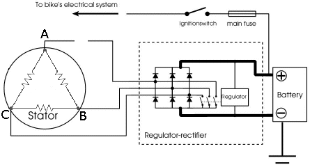
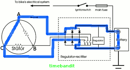
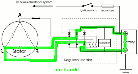
Like Greg said, the delta diagram makes it more obvious that you're down to one coil:
Standard Condition: 3-circuits:
AB:

AC:

BC:

Switched Condition: 1 circuit:
BC:

|
    
Sparky
| | Posted on Friday, May 11, 2012 - 02:16 pm: | 


|
I'm sorry to the OP for the sidetrack this thread has taken, but a big Thank You to all who pitched in to help me understand better the complexities of this system in the way H-D has chosen to mess it up. I, being more of a DC circuit guy, must admit I've got to study up more on AC generation and applications to get more familiar with the nuances of these circuits. Thanks for those links.
Hopefully others can benefit from these detailed discussions too.
In the meantime, I can't wait to get my R back from the dealer so I can order the oil-mod rotor from EBR and eventually remove that pesky relay. |
|