| Author | Message | ||
Timebandit |
Can anyone tell me the protocol number that buell used on the CAN bus? I'd like to do some sniffing. | ||
Aseecobra |
I haven't verified this with IDS or EBR but I suspect its ISO 11898-2 between the ECM and the IC. | ||
Timebandit |
The bike certainly has the 120R terminating resistors that are defined by 11898-2. I have read that H-D is presently using J1850-VPW. I was wondering if BMC might have used the same. I was thinking that because the 1125 was developed during BMC's parentage by H-D, that there might be some commonality. After all, Digital Technician 2 does communicate with all of the different bikes. There are quite a few different CAN Bus protocols. http://en.wikipedia.org/wiki/CAN_bus Does anyone know for a fact if/when H-D started using J1850-VPW, or what BMC actually used on the 1125? More to the point, it's not that hard to sniff using different protocols and figure out which one is in use. The hard part is going to be to decode the payload in the data frames, in the event that H-D has implemented a non-standard, non-compliant, proprietary code table. Anyone know how the data-frame packets are formatted? It would really be helpful to have a data table to translate the signals. With that, we could hack up our own on-board diagnostics.  (Message edited by timebandit on April 14, 2012) | ||
Ohsoslow |
its hard to say but it would be nice to know, oh the possibilities, hook extra gauges up utilizing the factory sensors would be nice. as far as i can tell Digital technician does not connect directly to the CAN bus it connects via a serial data connection to the ecm then to the CAN bus. | ||
Timebandit |
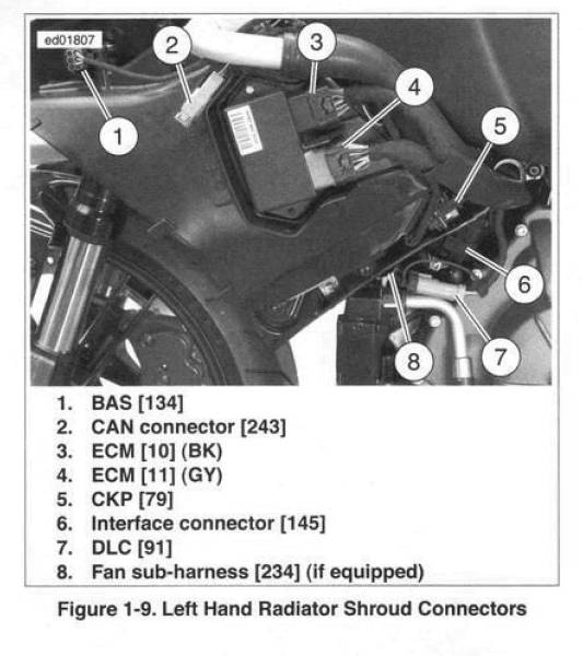
Under the left pod cover, right by the ECM there's a 2-pin Deutsch connector that holds the 120-ohm CAN-bus terminating resistor -- in other words, a direct access point to the Can-Bus for sending/receiving data.  According to the Electrical Diagnostics Manual, page 2-12, DT-2 hooks up at the serial Data Link Connector [91], and there is no direct connection between the IC and the serial data line; DT-2 accesses the ECM, and the ECM acts as a bridge to the CAN-bus. This means that there are 2 places that someone could tap into the data -- either at the serial DLC or on the CAN bus itself. Knowing the signalling protocols used for either one would be helpful. The doors that this could open are astounding. | ||
Aseecobra |
From what I could find, HD uses a Delphi based ECM and SAE J1850 is used between ECM and the dash. I recall that J1850 doesn't really have all the capabilities of CAN at least in the physical layer. (my former life with industrial canbus sensors) I suspect the Digital Technician II was designed to handle all Delphi and DDFI variants and accesses that data through the TTL serial connections on both brands of ECM. I couldn't find any info that it can connect to the CAN. Perhaps Buell had future intentions of adding devices other than the cluster. A perfect example is listed within the specs of the 1190RS which shows a DDFI-3 ECM and a power train control model. The PCM is probably on the CAN-BUS. I would think that everything that happens on the CAN-BUS with the DDFI-3 ECM is accessible through the serial connection. | ||
Mesozoic |
I have a Systec CAN-USB module I use to sniff a lot of CAN bus data. Plumbing CAN out shouldn't be difficult and sniffing for frames would be pretty straightforward as well. The question is, what baud rate is the Buell ECM running the CAN bus at and is it the standard or extended messaging format. Note that you can only stuff a maximum of 8 bytes into each CAN frame, although you can chain frames together using the FIFO flag. |