| Author | Message | ||
Gearheaderiko |
It might be the boot. It might be a faulty enrichener. But stock they run lean causing the much dreaded carb backfire and boot ripping. So at a minimum I would drill out the air mixture screw cap and adjust the screw to 2 1/2 turns out. Secondly, Switch to a #45 slow jet. Resist the urge to "give the carb a good cleaning" while you're there. | ||
Salvatorejrm |
Thanks for the advice. Why not clean the carb? Just wondering. | ||
Gearheaderiko |
Because a lot of people foul the reassembly and cause themselves more problems. It's also rarely necessary. | ||
Ezblast |
Merry Christmas!!!!!!  EZ | ||
Jr81212 |
I have a 2009 Blast, I am about to install the Jardine exhaust system. I live at 6700feet. What jets should I use? | ||
Ezblast |
45/175 | ||
Jr81212 |
Thanks! I am now having battery charging problems. No increase in voltage at battery when I rev engine , however I have 28 volts AC at the plug from stator to rectifier. Replaced rectifier/regulator with a used one still no charge. I can't find new voltage regulators for blasts. Do they exist new or is there a replacement/ alternative rectifier/regulator that works? | ||
Gearheaderiko |
Electrical is not my specialty, but try elsewhere on this forum or https://buellridersonline.com/forum/forum.php | ||
Jr81212 |
Thanks for the link | ||
Awf_hand |
So, last night I had to change my tail/brake light bulb. Easiest thing ever and I had the bulb in my cabinet as I had bought a two-pack for a car I had previously owned and only used one. I'm a big fan of dielectric grease and I used some of that as well. The '07 is still working well. Even has the original battery!! ________________________________________________ Firing order: 1 (Message edited by Awf Hand on May 18, 2018) | ||
Missionbolts |
Hi, just got in. Been out there riding 'other bikes', when I stumbled into a $200 wrecking yard special - an '05 Blast that had been wrecked at just under 10,000 miles. Landing on it's shifter jammed up the shift drum. Which I've since deburred and been riding. Not sure, just something about being able to wipe the mirrors off at stoplights without needing to move my hands around - but I think the counter-balancer isn't working right.... Anyways, the speedometer quit on me a few weeks ago. In trying to decide if I need to replace the head unit or just the sensor, I found that the wiring diagrams are getting a couple pins backwards This is for the connector on the back of the sealed speedometer module itself. There's three wires for the speed sensor on pins 9, 10 & 11 The manual shows pin 10 being 'Speed Power' and pin 11 as 'Speed Return' 'Speed Power' is the red wire at the sensor, and it goes to pin 11 on the speedometer. You can see this by looking at the color of the wires and the pin numbers cast into the back of the plug Pin 9 is the signal, but there's a little something extra going on with this pin. Inside the speedometer, there's a industry standard pull-up resistor boosting the signal line so it has a positive voltage with the sensor unplugged When the sensor is plugged in, and a geartooth or something gets in it's sensing range, it connects the signal line to ground The pull-up inside the speedometer is purposely made small enough that it can't keep the voltage from dropping, and you will see less than a volt Without the geartooth, or when the sensor is unplugged, the signal line will have well over 6 volts. But because of how the pull-up circuit works, the exact voltage will always be a percentage lower than whatever the battery voltage is In my case, if I measure 12 volts on pin 11, I get 9.89 volts on pin 9 I cut apart the old sensor. I'll be rebuilding that with a much better hall sensor. The old sensor is an Allegro with these numbers: D459JPC 665 0450 I couldn't find anything on it, but judging by how many of these sensors seem to be dying, I think I'll be much better off doing this my way I already had a handful of sensors from a project I did years ago. I'm using one of thesehttps://www.mouser.com/ProductDetail/Melexis/MLX90 217LUA-CAA-000-BU?qs=KuGPmAKtFKWjUVEf6U%252bOdw%3D %3D Just glue a magnet on the back and cast the thing into place with some non-metallic epoxy (no JB Weld!) The sensor housing has it's internal support pins crossed, so it's a good idea to check which wire goes to which. The white wire is connected to the middle pin, which is not the standard pin layout for hall effect devices. So I'll be doing some bendy pin gymnastics using my forceps, to crisscross the signal & ground leads. It helps to solder the power in place first I've had the speedometer connected to a breadboard on my workbench, with a spare sensor. For triggering, I made a tonewheel using a 4" cutoff arbor and some random roundy steel thing I chopsawed some notches into, chucked into a hand drill and spun that really close to the sensor Without a load, my drill only runs just a bit under 1700RPM's according to my oscilloscope(1666.6666 based on the pulse pattern I was getting). The tonewheel has 36 teeth and with that combo the speedometer only reads 25 MPH. Slowing the drill down gets a slower speed reading on the speedo By the way, I also tested every other pin. Some I connect to pin 8: reset oil & neutral. The rest I connect to pin 12. Lights up like it's christmas time! It's one thing to think the turn signals are showing for both sides while I'm riding, but when it's all on the bench and I'm not busy staring death in the face, now I see that there's really only the one LED that lights up for either left or right turns. Fixing that means cutting the seal and more messing around. Or I can just ignore that. One less LED = lighter bike! (Message edited by missionbolts on June 26, 2018) | ||
Missionbolts |
Ok, just an update on my rebuild of the speed sensor, part #74431-01B 1st off, the rebuild is done and works just fine. Here's a few pics to help explain what all happened This is the sensor cut down to just above the o-ring groove & with the hall effect device unsoldered and removed: 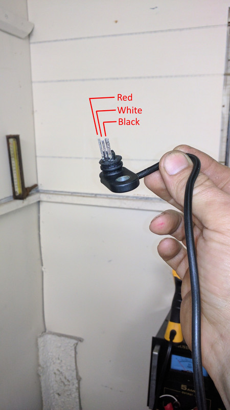 If I did this again, I will leave a lot more above the groove, maybe 1/4". The pin ordering is unconventional, the ground would usually be the middle pin Turned a bar of beeswax to make an impressionable plug gauge: 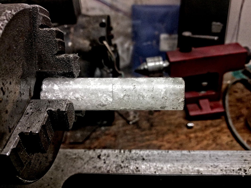 This wax rod fit loosely in the sensor hole on the bikes engine. I held the rod snugly against the gear inside while turning the rear wheel. This caused the gear to scrape of a bit of wax & left an impression to show me exactly how centered the gear is to the sensor. But more importantly, this is how I got an exact measurement of just how far the gear teeth are from the sensors mounting flange. I cut a line into the wax, using a razor blade. This was 1.214" Marks left in the wax: 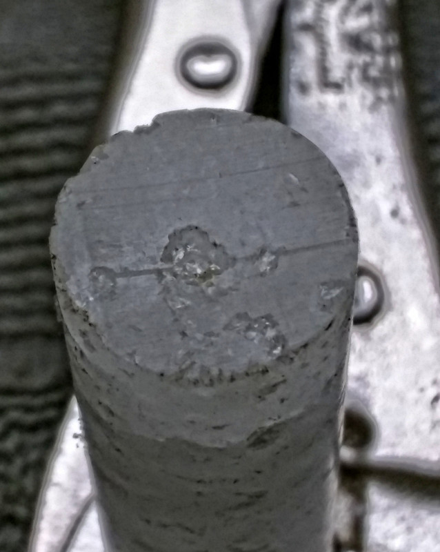 The flat spot on the side is from the wax rod being loose enough to sit that far off center, with the gear teeth dragging it to that side. Judging by what I see here, the gear & sensor are in perfect alignment to each other Using a drillpress to keep things square & steady: 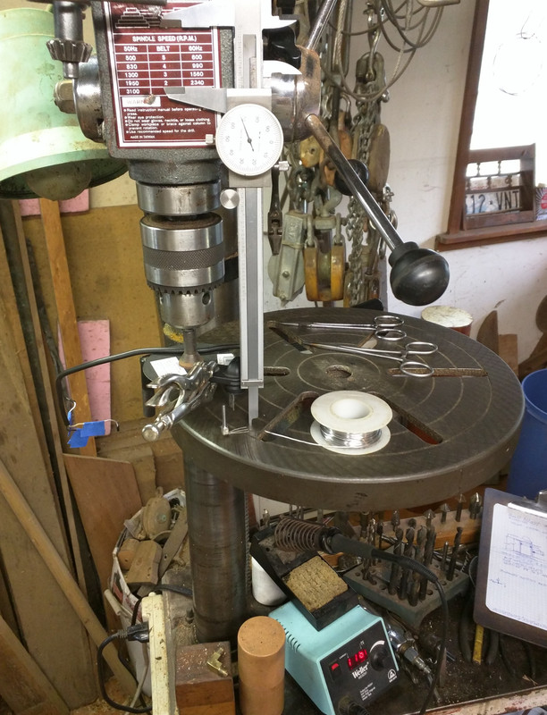 Height was approximately 1.16" The magnet on the hall device comes in very handy here, as it grabs the cast iron table just perfectly. Later, I wrapped the drill chuck with masking tape, to keep it from rotating The pins for the ground & signal output are bent, until they lay up neatly against the soldering points: 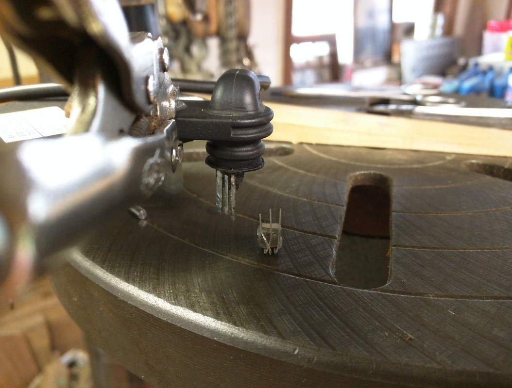 Cutting down the magnetic pole piece: 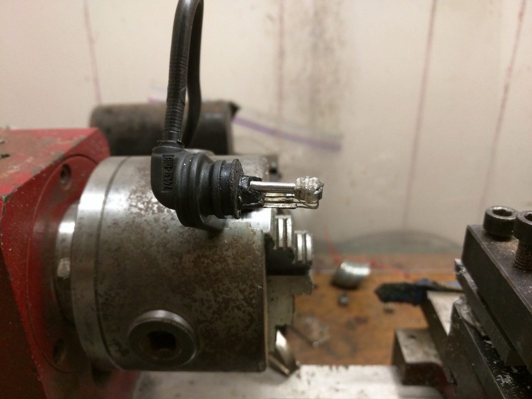 I wanted the magnetic field to extend out a bit further in front of the sensor, so I added a small bit of permalloy I hacksawed out from the back of a junked car speaker. This is permalloy, which conducts magnetic fields better than plain steel. I turned the chunk into a rod, then shortened it until it fit between the stack of magnets and the plastic housing. Hotglue keeps everything from shifting until I can cast it permanently in epoxy. The hotglue is soft, so that might even help absorb shocks & vibrations which could potentially break the solder joints apart. Or it will allow the parts to move around too much and break the joints apart that way... Another view of that: 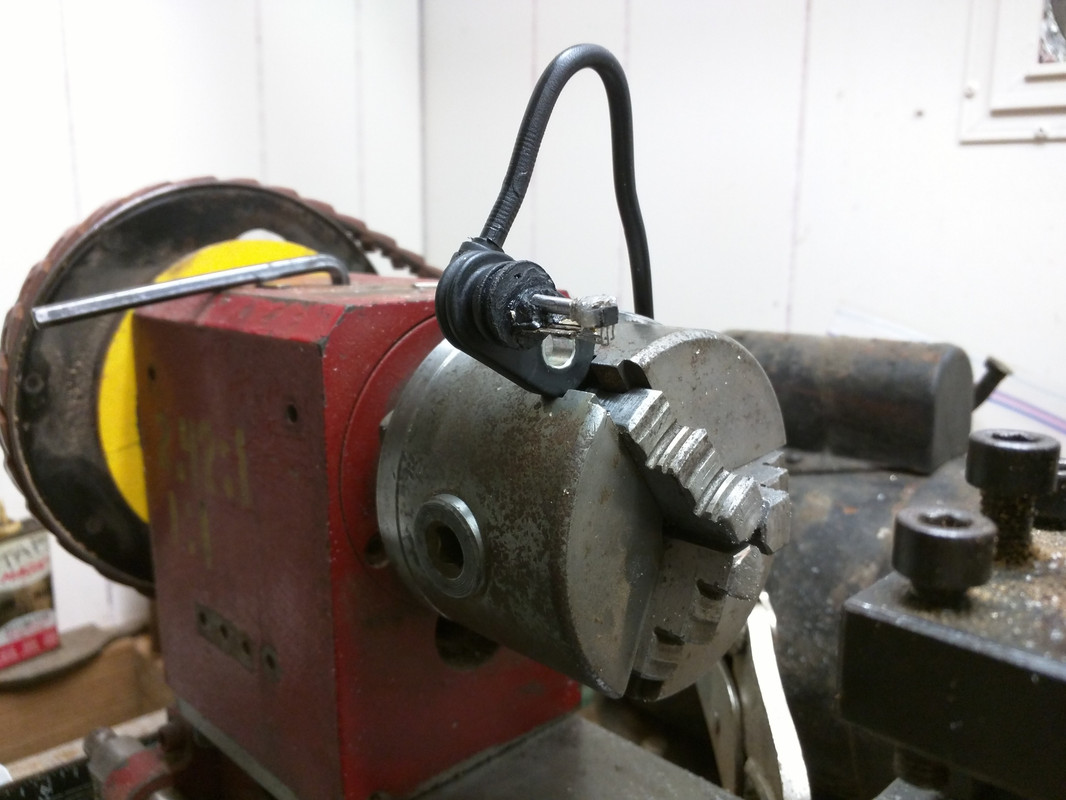 After deciding against getting too carried away with making a split mold to recast the barrel on the housing, just wrap it with masking tape: 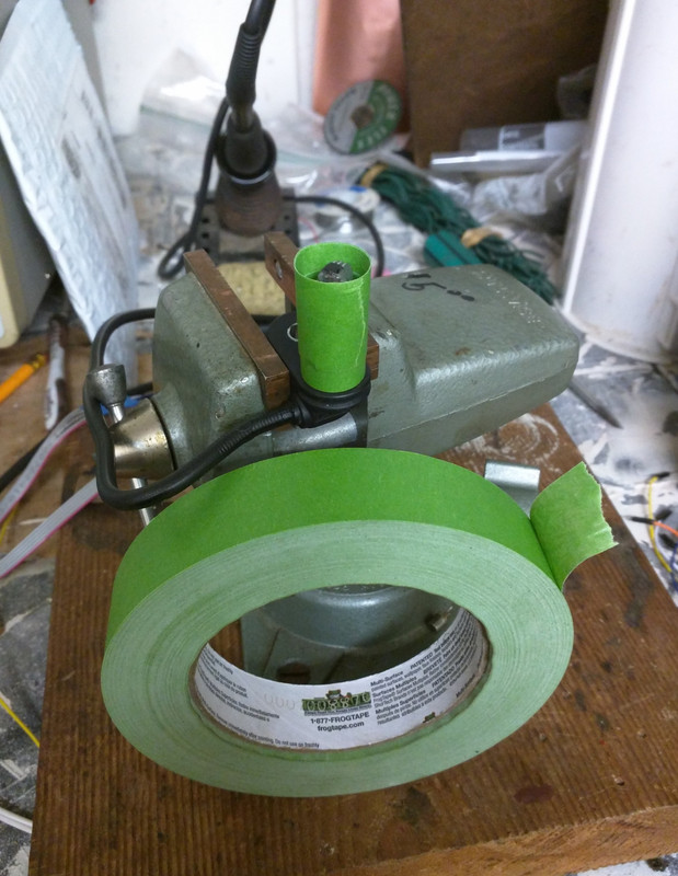 Then filled that with epoxy: 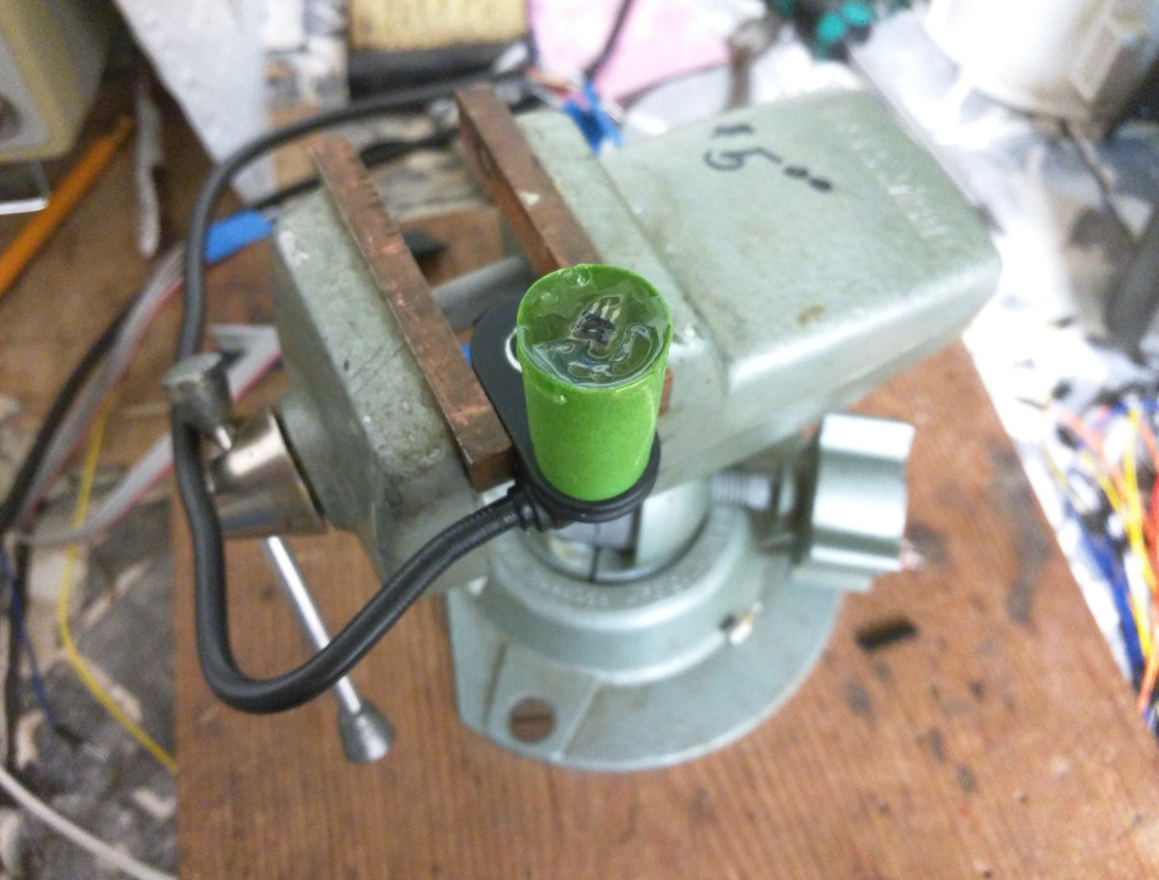 I used West Marine G-Flex 655 because it was what I had. It's too thick for getting down inside a cavity like this, but I settled it in place with a toothpick until most of the worst air pockets were worked out. This epoxy is much better than the home improvement stuff, for general repairs. Even works underwater Tape freshly removed, showing a few bits that need trimming down: 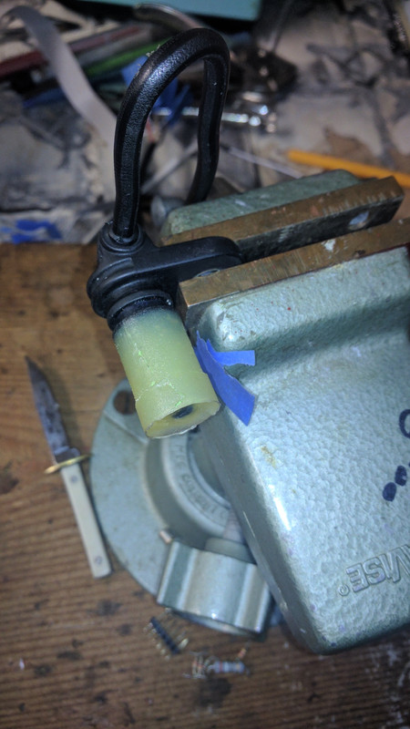 I just handheld this on a 10" stationary disk sander, very lightly to remove the step in diameter & then to square off the end and bring it down flush to the hall devices face. A wider masking tape would have been better, but the sensor fit just fine on the 1st try. The o-ring ought to be doing it's thing like it always had Tone ring: 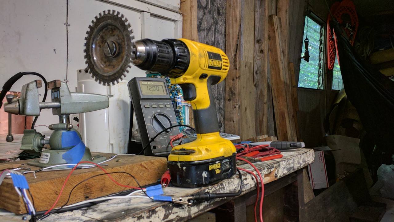 5-pin test cable: 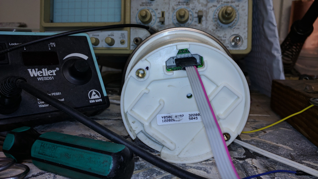 Breadboarded testing: 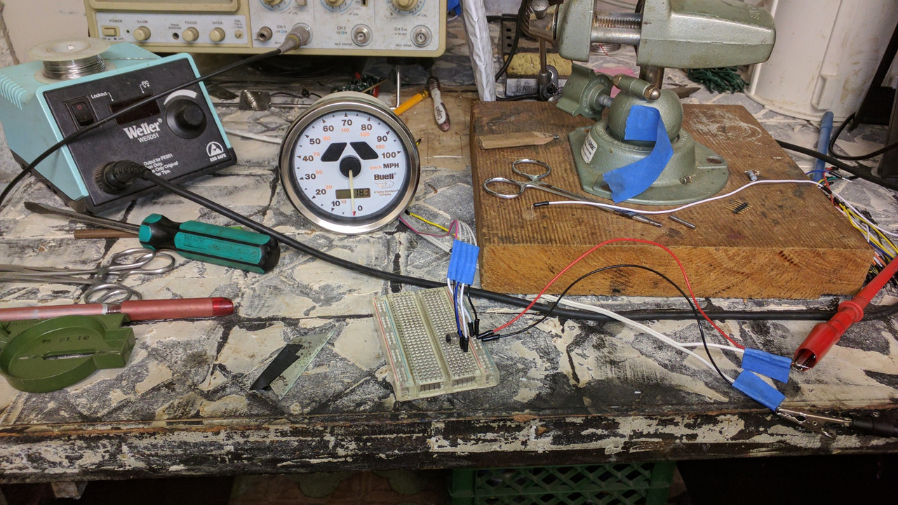 On the breadboard is the hall device, with magnets attached. If I had more hands, the speedometer would be reading 25 in this shot Then I took a junk IDE hard drive cable and cut it down into a 12-pin test cable: 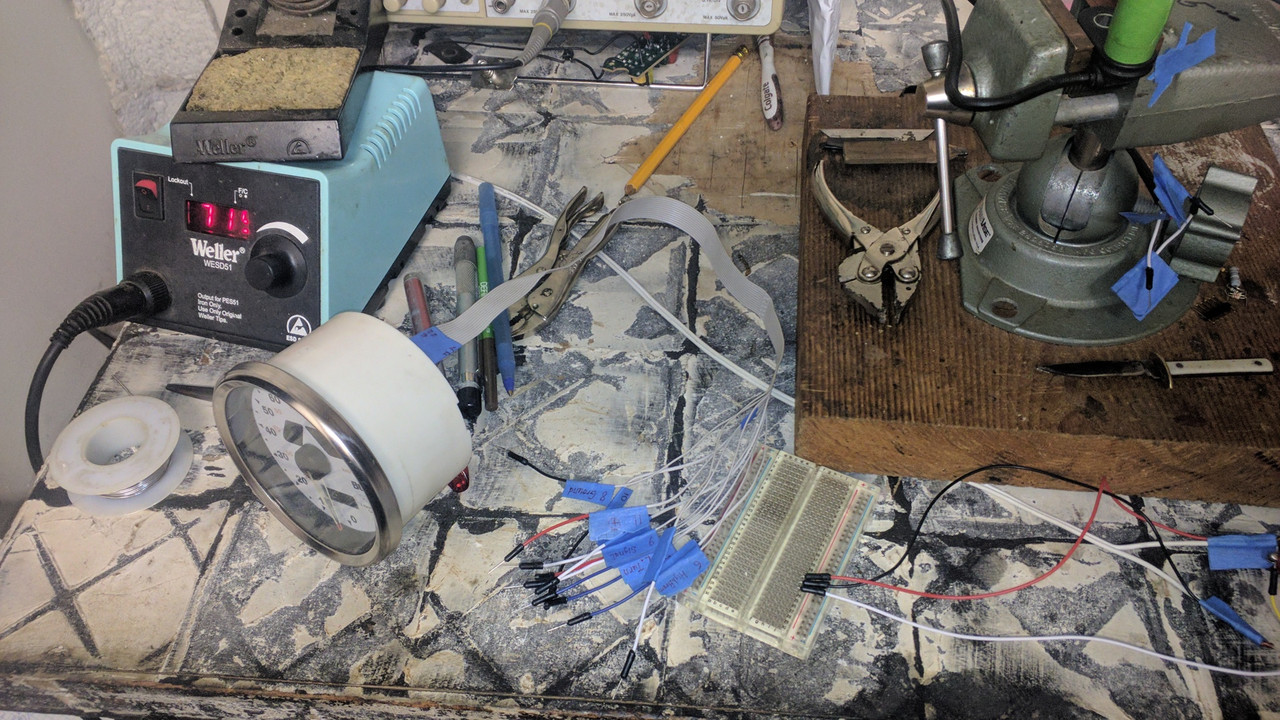 All lit up: 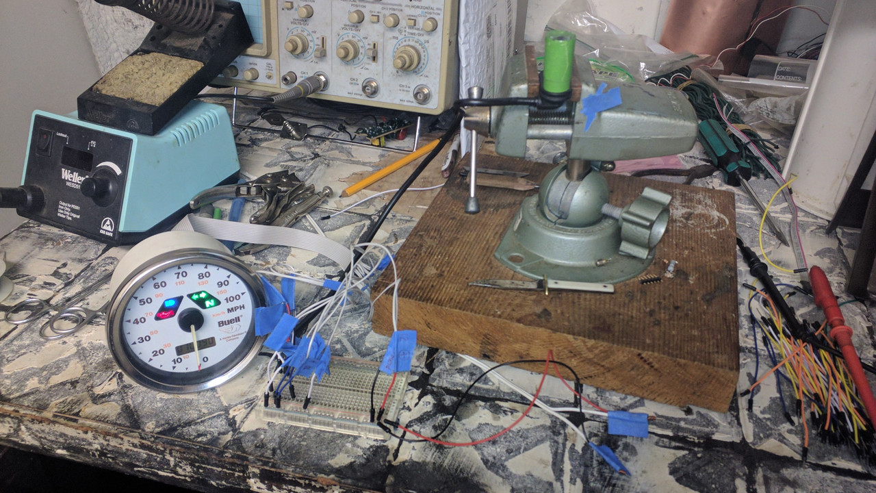 If I get inspired enough, I suppose I could hook this up to an Arduino or maybe an STM32 and make my own version of the HD speedometer test tool. But mine would be way better! Anyways, this rebuild turned out to be a lot easier than I was expecting. Total cash outlay somewhere around $5. Time involved could be just a weekend if I wasn't such a slacker. Digikey has all the hall effect sensors you could want. I chose an automotive rated part that has automatic calibration for the magnetic field strength. That way I didn't need to spend that much time getting the magnet to work right. I put a link to the part number on a previous post Now to do the endurance testing. Get back to me in a year to ask how this holds up, but now I've got some riding to get on with  | ||
Muddhorn |
Crankshaft, NO SPLINE QUICK FIX stator nut loose, movement ground splines to smooth crank. Remove 4 bolts from inside stator holding onto gear. Drill out 4 holes from gear side to just at thread inside. Use paper clip to measure where bolt ends and only drill that far in. YOU MUST USE A 9/32 COBALT/ TITANIUM BIT. It's hardened steel, Use 1/4 20 tap to clean threads thru to old threads.Make a steel plate the size of four holes, drill a 5/8 hole for crank. All must be exact, MEASURE CAREFULLY. Mig weld plate to crank, then for clearance problem. You must remove some of the inner primary cover brace web. Just rotate engine and check where it hits cover. I'll send all pics if needed, just text me. I'm trying to upload photos | ||
Gearheaderiko |
Nice. | ||
Kmbuell |
Canít wait to take that motor apart! Seems a bit severe cranks canít cost that much or put another motor in it | ||
Awf_hand |
Has anyone ever changed the transmission lubricant on one of these? I found something on the web that had some directions but, dang. If there is a way to do this without taking the whole thing apart I'd prefer that. _____________________________ Firing order: 1 | ||
Gearheaderiko |
Drain it out the drain plug (not the chain adjuster) and fill it through the transmission vent line,(which takes forever, but no more longer than it takes to pull it apart). It takes exactly 1 quart. Drain it hot. | ||
Awf_hand |
Thanks Gearheaderiko! Now for the next question. I lost my shift lever and the little splined drum it rides on. It was an adventure riding home in 5th gear as is came off somewhere on a 35 mile stretch of interstate and I didn't realize it until I went to downshift on the offramp. Where can I buy another one? _______________________ Firing order: 1 | ||
Gearheaderiko |
Well, thereís some very expensive Blast shifters on eBay. :-( Sportster lever works, theyíre just shorter. Bad if you have big feet or big boots. | ||
Deemster |
Need to know the thread size for the stator mounting holes on a 2002 blast. The stator came loose and sheard off all the bolts. I removed the broken pieces. I want to buy the correct tap to clean up the threads. Has anyone else had this happen? If so what precautions did you take what reassembling the stator? Thx Greg | ||
Missionbolts |
Deemster - if it's the same as my '05, which I assume it will be, my '05 parts manual has that listed as a 10-24 x 1" | ||
Deemster |
Missionbolts-Thank you for the info. | ||
Deemster |
Is there a preferred engine oil and primary oil everyone uses? Oil change is two quarts and primary is one quart from everything I have read. Is this correct? Thx | ||
Gearheaderiko |
Synthetic 20w-50. Oil change is 1.5 quarts. Add 2 quarts and it will be overfilled. So start at 1.5 and check again when HOT! Trans is 1 quart, exactly. | ||
Deemster |
Is that with or without filter change? Also what are the torque values for the clutch nut and compensator nut? I have read many articles and there seems to be many different answers. | ||
Gearheaderiko |
With filter. Seriously, it takes a ridiculously small amount of oil. 3/4 qt is left in the crankcase when you change the oil. Clutch nut and compensator nut? Technically, what I think you mean is not what they are called. Can you clarify? | ||
Deemster |
Gearheaderiko thank you for the info on oil change. I have downloaded a 2002 P3 service manual and it has the torque info i need. The LH Clutch mainshaft nut is 70-90 ft/lbs and the engine sprocket nut is 190-210 ft/lbs. | ||
Ezblast |
https://www.useforce.com/product/buell-exhaust-for-buell-blast/?fbclid=IwAR2G0dbTJOQI8_fzge_pyB-zb0hv-hZdyeyC_hgPt9CCyr3Sja4mSR3SJSA 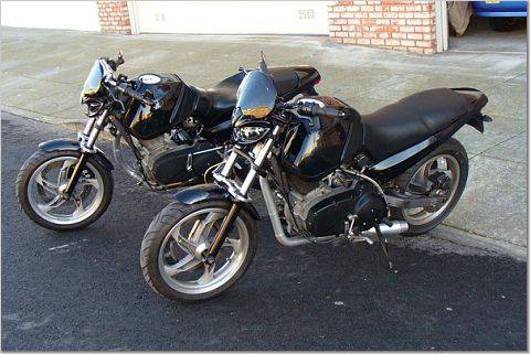 The front Blast - Starkiller - is running a Force exhaust with silver powdercoating - an expensive extra. The trick is the mounting - add rubber bushings to the rear and mid-mounting points, using stock exhaust hardware also at the mid mounting point. It is a seriously tuned system for top end and delivers, with only my LSR set up on Vader - the rear Blast - being even better. EZ |